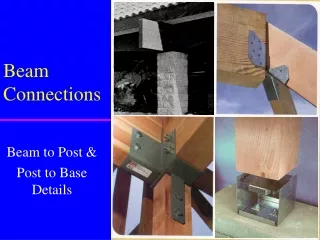
Beam Connections
Beam Connections. Beam to Post & Post to Base Details. Beam Connections. Beam connections involve a condition where a uniformly distributed load is concentrated through a beam/column condition, then to a pad of concrete (FTG) & subsequently distributed to the ground. BENDING.

Beam Connections
E N D
Presentation Transcript
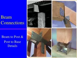
Beam Connections Beam to Post & Post to Base Details
Beam Connections • Beam connections involve a condition where a uniformly distributed load is concentrated through a beam/column condition, then to a pad of concrete (FTG) & subsequently distributed to the ground
BENDING Factors Influencing Beam Connections • Weight (LL & DL) • most important • based on tributary area & load • Wind Loads • Seismic Loads • Snow Loads • Material Type • wood, steel, masonry • length influences bending
Hole Placement for Columns/Beams • Distance Equals: • 7 x diameter • to end • 4 x diameter • to edge • 4 x diameter • between holes
Maximum Hole Size for Beams • Maximum Hole Size Equals = 1/5 width or height of beam X = width or height of beam
Uplift • Any overhang (including an open garage) is subject to UPLIFTfrom the wind • can’t rely on weight of structure alone to hold in place • To preventUPLIFT: • metal post caps and metal post base • Post cap means to bolt beam to column • Post base means to bolt column to footing in ground • hurricane clips and seismic ties • metal angles to attach truss/rafter to wall framing
Post Caps • Used to connect or provide a transition of loads between columns and beams • Engineered to withstand uplift and lateral forces • forces or loads are measured in KIPS = 1000 lbs • Three structural divisions of post caps (metal gauge of caps are different, designs similar) • 1) heavy weight • 2) medium • 3) lightweight
Beam Conditions and Post Cap Designs • Connection 1--Beam at end or corner • Connection 2--Continuous beam • Connection 3--Spliced beam • Connection 4--Four-way beam intersection • Connection 5--Tee and Ell brackets
Common Post Caps (Connection 1) • Beam at end or corner
Common Post Caps (Connection 2) • Continuous beam
Common Post Caps (Connection 3) • Spliced beam
Common Post Caps (Connection 4) • 4-way beam intersection
Common Post Caps (Connection 5) • Tee’s & Ell’s brackets • Connection types • continuous, splice, end
Post Bases • Used to connect posts to the concrete base below • Usually metal • A wide variety of types • Selection depends upon • 1) Size and material of column • 2) Environment (dry or wet) • 3) Weight or loads upon column
Post Connections andPost Base Designs • Connection 1--Pocket design, welded plates and angles • Simple post base • Connection 2--Angle straps with shear plates • Connection 3--”U” shaped anchor strap • Connection 4--Clip angles
Common Post Bases (Connection 1) • Pocket design, Simple Post Base • welded steel plates • column inside • preset anchor bolts • vent for moisture
Common Post Bases (Connection 2) • Angle Strap with Shear Plates • shear plates • prevent splitting • bearing plate • metal straps • anchor bolts
Common Post Bases (Connection 3) • Anchor strap • U-shape • preset in concrete • most common
Common Post Bases (Connection 4) • Clip angles and bearing plate
Additional Post Base Connections • Adjustable Elevated Heavy Section
Detailing Beam/Column/Footing Connections • Detailer must know • size of beam • size of column/post • type of post cap • size/number/location of bolts • Material type • wood, steel, concrete, or masonry • Height of column • Type of post base • Soil bearing capacity • Footing size
Detailing Beam/Column/Footing Connections • Standard Tables or Manufacturer’s are literature used to find acceptable load vs column height Examples: Height Size Loads 4’ 4x4 14,700 lb 8’ 4x4 8,304 lb
Pipe Column • Commonly used to support beams • May be fixed length or adjustable • Cap & Bearing plate usually are welded to pipe column • Attach to footing pedestal via anchor bolts • Dry Pack • moist cement between bearing plate & footing pedestal to assure perpendicularity
New Notation • 3” x 7.58 PIPE COLUMN Old Notation Pipe Column Callout • 3” PIPE COLUMN 7.58#, meaning: • 3” = nominal pipe diameter • 7.58# = weight/foot • a 6 ft length would weigh 45.48 lbs and would carry 38 kips (see table pg 411)
Masonry Columns • Used in same manner as wood/steel columns • Design Rules • unsupported, reinforced masonry columns not to exceed 10 times smallest cross-sectional dimension • hollow unsupported masonry columns not to exceed 4 times smallest cross-sectional dimension • joints should “lap” normally, no vertical joints • Examples: 16”x16”reinforced column max height = 10 x 16 =13.3 ft • 24”x24” hollow column max height = 4 x 2 = 8 ft (10 x 16” = 160”/12 = 13.3ft)
Masonry Columns • Note steel saddle to connect beam to concrete • Reinforcing & grout in cavity
Pilaster • A “column” built into masonry wall • for beam support • used to give lateral support to wall
ASSIGNMENT • Develop the following details for sheet S-3 • 1/S-3 wall to truss connection (use a simpson H1 anchor) • 2/S-3 shear wall detail (1/2” plywd on 1 side of prefab truss and interior shear wall, be sure that the truss is directly over the shear wall • 3/S-3 2”x6” block between trusses at walls • 4/S-3 Simpson strap LSTA24 each side of ridge on 5/8” gyp brd w/ 20 ga sht mtl 8’on 8’ off ridge use (2) rows 6d nails 5” o.c. • 5/S-3 Use a simpson strap LSTA24 on each side
Drafting Exercise Pipe Column Detail • Change pipe column callout to new notation • 3” X 7.58 PIPE COLUMN • Add callout for rebar in footing • 2-#4 REBAR EACH WAY • Add 3/4” fiber expansion board between concrete walk and footing pedestal • Scales as shown in text • Pipe Column to Beam Detail