Download
1 / 36
450 likes | 1.18k Views
What is a signal ?. A function of one or more independent variables which contain some information. Voltage, Current ,temperature are all different signals. Thus signal is a mathematical representation of any physical energy. Objectives. What is signal , its types What is modulation

E N D
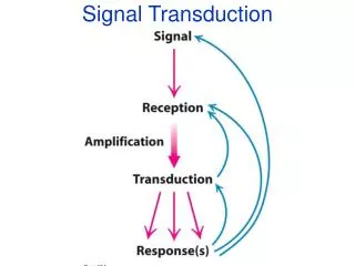
What is a signal ? • A function of one or more independent variables which contain some information. • Voltage, Current ,temperature are all different signals. • Thus signal is a mathematical representation of any physical energy .
Objectives • What is signal , its types • What is modulation • Why is modulation done • Sampling theorem • Detailing about sampling theorem • Communication systems • Types of modulation
What is modulation ? • It is a process in which some characteristics of a signal called carrier signal is varied in accordance with the value of the message signal. • The message signal is also known as modulating or baseband signal • The resultant signal after modulation is known as modulated or bandpass signal. Carrier Wave Modulating Signal
Why use modulation ? 1)To achieve practicality of antenna The dimensions of transmitting antenna is limited by the wavelength of the signal it can transmit. 2)To remove interference
Types of modulation • A carrier wave can be described by 3 parameters: amplitude, frequency and phase. v(t) = A sin (ωt + φ) A=amplitude ω=frequency φ=phase Thus we can have :- Amplitude Modulation Frequency Modulation Phase Modulation
Amplitude Modulation • It is a process in which amplitude of the carrier wave is varied according to message (modulating) signal. • In the process of amplitude modulation the frequency and phase of the carrier wave remains constant. Carrier wave Sinusoidal modulating signal Amplitude modulated signal
Suppose Carrier wave ,c(t)= Ac cos ωct (baseband) Modulating signal , x(t)= V cos ωmt Amplitude Modulated wave is given by :- s(t)=AC cos (2π fCt) {1 + m cos (2π fmt)} where AC= unmodulated peak carrier amplitude fm = modulating frequency fC = carrier frequency m= modulation index ( degree of modulation) the value of m must be between ‘0’ and ‘1’ .
Modulation Index • Indicates by how much the modulated variable varies around its 'original' level. • In terms of AM it can be defined as the measure of extent of amplitude variation about an unmodulated maximum carrier. • also known as modulation depth • For AM , • m= peak value of modulated signal V ------------------------------------------ = ------ amplitude of carrier signal Ac
Frequency Modulation • It is a process in which frequency of the carrier wave is varied according to message (modulating) signal. • In the process of frequency modulation , the amplitude and phase of the carrier wave remains constant. Carrier wave Sinusoidal modulating signal Frequency modulated signal
Suppose carrier wave , c(t)= Ac cos ωct Modulating signal ,x(t)= V cos ωmt Frequency modulated wave is given by :- v(t) = AC cos {2π fCt - m sin(2π fmt)} where AC= unmodulated peak carrier amplitude fC= carrier frequency fm= modulation frequency m = modulation index (“degree” of modulation) In case of FM ,modulating index describes variations in the frequency of the carrier signal. m = ▲f ------ where ▲f is the peak frequency variation fm
Digital Modulation – Analog signal carrying digital data
Amplitude Shift Keying • The amplitude of an analog carrier signal varies in accordance with the digital (modulating signal), keeping frequency and phase constant. • The level of amplitude can be used to represent binary logic 0s and 1s. We can think of a carrier signal as an ON or OFF switch. • In the modulated signal, logic 0 is represented by the absence of a carrier and logic 1 is represented by the presence of a carrier , thus giving OFF/ON keying operation and hence the name given. • The ASK technique is also commonly used to transmit digital data over optical fiber
Carrier Cos(2fct) OOK output Acm(t)Cos(2fct) Message m(t) On-Off Keying (OOK) Modulating Signal ,m(t) Modulated Signal • The complex envelope is • The OOK signal is represented by
Phase-shift keying (PSK) • A digital modulation scheme that conveys data by changing, or modulating, the phase of a reference signal (the carrier wave). • PSK uses a finite number of phases, each assigned a unique pattern of binary digits. • Two common examples of phase shift keying are :- Binary shift keying which uses 2 different phases Quadrature phase shift keying which uses 4 different phases.
Message: m(t) Carrier:Cos(2fct) BPSK output AcCos(2fct+Dpm(t)) 180 Phase shift 1 0 1 0 1 0 1 Message m(t) Unipolar Modulation m(t) Bipolar Modulation s(t) BPSK output Binary Phase Shift Keying (BPSK) Generation:
Receiver Transmitter
QPSK defined using Constellation Diagram Constellation diagram for QPSK with Gray coding. Each adjacent symbol only differs by one bit.
Message: m(t) Cos(2f1t) FSK output AcCos(2f1t+1) or AcCos(2f2t+2) Osc. f1 Cos(2f2t) Osc. f2
OtherForms of FSK • MSK • Audio FSK
Minimum Frequency Keying MSK = 0.25 fm, where fm is the maximum modulating frequency. As a result, the modulation index m is 0.25.
Audio Frequency Shift Keying digitaldata is represented by changes in the frequency (pitch) of an audio tone
Quadrature amplitude modulation • (QAM) is both an analog and a digital modulation scheme. • It conveys two analog message signals, or two digital bit streams, by changing (modulating) the amplitudes of two carrier waves, using the amplitude-shift keying (ASK) digital modulation scheme or amplitude modulation (AM) analog modulation scheme. These two waves, usually sinusoids, are out of phase with each other by 90° and are thus called quadrature carriers or quadrature components — hence the name of the scheme. The modulated waves are summed, and the resulting waveform is a combination of both phase-shift keying (PSK) and amplitude-shift keying (ASK), or in the analog case of phase modulation (PM) and amplitude modulation. In the digital QAM case, a finite number of at least two phases, and at least two amplitudes are used. • QAM is used extensively as a modulation scheme for digital telecommunication systems.
Sampling • A mechanism for converting continuous signal to discrete time signal. • Acc. to sampling theorem :- A continuous time signal may be completely represented in its samples and recovered back if the sampling frequency is fs≥2fm ,where fs is the sampling frequency and fm is the maximum frequency present in the signal.
Pulse Modulation • In this case the carrier wave is no longer a continuous signal but consists of a pulse train whereas
Pulse Amplitude Modulation • In PAM, the amplitude of the carrier pulse train is varied in accordance to the modulating signal. Pulse Width Modulation • In PWM , the width of the pulses is proportional to amplitude of modulating signal. Pulse Position Modulation • In PPM , the position of the pulse with reference to the position of reference pulse is changed according to the value of the modulating signal.
Pulse Code Modulation • It is a digital pulse modulation system. • The output of PCM is in the coded digital pulses of constant amplitude ,width and position . • The basic operations in PCM are :- Sampling Quantization Encoding
Sampling Quantization Encoding • Quantization – It is a process of dividing the total amplitude range into number of standard levels. • Encoder – It basically converts the quantized input signal to binary words.