Download
1 / 2
20 likes | 129 Views
1.5.14. If the tunnel is straight, it is easier to see light at its end. Long Optical Path Flow Cells. Garth’s Cell. Liquid Core Waveguide. Water RI= 1.33 (n2) fluoropolymers RI= 1.29 (n1). PEEK. I.D. 0.5mm. I.D. 0.8mm. PEEK. Up to 50cm @ I.D. 0.5 mm. Straight. Coiled or bent.

E N D
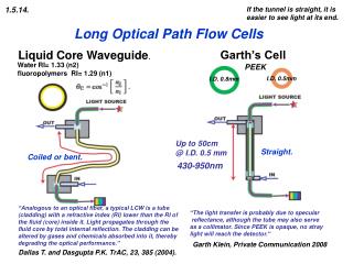
1.5.14. If the tunnel is straight, it is easier to see light at its end. Long Optical Path Flow Cells Garth’s Cell Liquid Core Waveguide. Water RI= 1.33 (n2) fluoropolymers RI= 1.29 (n1) PEEK I.D. 0.5mm I.D. 0.8mm PEEK Up to 50cm @ I.D. 0.5 mm Straight. Coiled or bent. 430-950nm “Analogous to an optical fiber, a typical LCW is a tube (cladding) with a refractive index (RI) lower than the RI of the fluid (core) inside it. Light propagates through the fluid core by total internal reflection. The cladding can be altered by gases and chemicals absorbed into it, thereby degrading the optical performance.” “The light transfer is probably due to specular reflectance, although the tube may also serve as a collimator. Since PEEK is opaque, no stray light will reach the detector.” Garth Klein, Private Communication 2008 Dallas T. and Dasgupta P.K. TrAC, 23, 385 (2004).
A 0.65 B 0.22 1.5.15. Experimenting with Garth's Cell Since even the most recent reviews of photometry do not describe anything remotely similar to Garth cell design (Frenzel and McKelvie 2008, Dallas 2004) it was irresistible to question and test Garth’s idea. Here I present a simple experiment with a dye (bromothymol blue in 0.01M borax pH 9.2) injected into carrier solution (0.01M borax) and monitored at 620nm. The apparatus was micro SI with LOV module (see Chapter 4 on SI-LOV technique) since Sequential Injection allows automated increase of the injected sample volume. Two experimental runs are shown superimposed. One (A) with 30 cm long Garth cell (green PEEK I.D. 0.8mm) mounted on LOV module and the second (B) with 1 cm long LOV flow cell path (I.D. 1.6 mm). BTB solutions of concentration ratio 1:10 were used, while the flow cells had light path lengths ratios 30:1 Since A/B slope and absorbance ratios are 3/1 absorbance increases linearly with cell length. Surprisingly Garth cell can be, up to 10 cm length, operated with LED, while tungsten lamp provides sufficient light intensity up to 50 cm long light path. Garth cell is not fouled, even when used for real life assays such as nitrate, nitrite, orthophosphate and ammonia. It is refreshing to see a simple viable alternative to be discovered in an area, that seemed to be well searched, thoroughly discussed and even patented. Now, when we have an alternative to LCW technology, it will be interesting to see its acceptance and further investigation and questioning. http://www.flowinjection.com/Brochures/sma_ULP.aspx A@620 A B Injected volumes: 10, 20, 30, 40, 50 & 60mL A: 0.0004%BTB, 30cm flow cell B: 0,004%BTB, 1 cm flow cell A/B= 3/1 Dallas T. and Dasgupta P.K. TrAC, 23, 385 {2004) W. Frenzel I. D. McKevie: Photometry Ch 12 in S. D. Kolev, I. D. McKevie Advances in FIA and Related Techniques Elsevier Amsterdam 2008