Download
1 / 33
330 likes | 507 Views
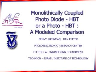
Monolithically Coupled Photo Diode - HBT or a Photo - HBT : A Modeled Comparison. BENNY SHEINMAN, DAN RITTER MICROELECTRONIC RESEARCH CENTER ELECTRICAL ENGINEERING DEPARTMENT TECHNION – ISRAEL INSTITUTE OF TECHNOLOGY. Workshop outline. Introduction.

E N D
Monolithically Coupled Photo Diode - HBT or a Photo - HBT : A Modeled Comparison BENNY SHEINMAN, DAN RITTER MICROELECTRONIC RESEARCH CENTER ELECTRICAL ENGINEERING DEPARTMENT TECHNION – ISRAEL INSTITUTE OF TECHNOLOGY
Workshop outline • Introduction. • Phototransistor electrical configurations. • General bandwidth / efficiency limitations in a photo-detector. • Additional limitation in a top illuminated PIN diode / phototransistor. • Electrical modeling of the top illuminatedPIN diode / phototransistor.
Phototransistor configuration Common Base Hole current flows to ground no current gain
Phototransistor configuration Common Collector High current gain Low output resistance limits performance.
Phototransistor configuration Common Emitter High current gain. Bandwidth limited by Miller effect:
Miller Effect Integrated PIN HBT Phototransistor
Cascode Configuration Performance comparable to that of a PIN + HBT ?
650nm Collector 150nm Collector 250 250 F 200 200 t F 150 150 max F Frequency [GHz] Frequency [GHz] t 100 100 F 50 50 max 0 0 0 0 50 50 100 100 150 200 150 250 200 300 2 2 Current Density [KA/cm ] Current Density [KA/cm ] Kirk effect
Kirk effect (cont.) Associated time constant for a 1*10 emitter and a 10 diameter optical window:
Photodetectors bandwidth limitations • Carrier transit time: • RC of detector capacitance and amplifier input resistance: M. Agethen et al. IPRM 2002
Ideal Amplifier Only transit time limits performance
Base-collector junction in a phototransistor GaInAs active layers: Base layer highly resistive -
Additional RC filter bandwidth limitation in a top illuminated PIN diode / phototransistor.
r0 dr r R1 R2 R3 RN C1 C2 C3 CN Io1 Io2 Io3 IoN I2 I4 I3 I1 RC network in a PIN detector Physical structure Electrical equivalent circuit
Top illuminated photo-transistoroption 1 Optical window Emitter Contact To base Base Metal Base Mesa
Emitter Base Metal Base Mesa Top illuminated photo-transistoroption 2 Optical window Contact To base
Spot size radius =12.5 2 12.5 Internal contact
48 0.2pF Model of top illuminated detector Solution of current equations is difficult: - distributed photocurrent • Photodiode capacitance / area Yet for a known capacitance value, a single pole fit gives good results
High efficiency phototransistors • Cover optical window with conducting transparent ITO (Indium Tin Oxide) layer. • Place internal and external contact to the diode: • Backside illumination.
Overcoming the limitations Incorporating novel structures in photo-transistors: • Wave guide photodetectors • Distributed phototransistors • Resonant-cavity-enhanced photodetector. • Uni-traveling-carrier photodiode.
Conclusions • In the cascode configuration, photo-HBT have comparable performance to PIN detector + HBT processed from the same layers. • PIN detector + HBT processed from different layers will have superior performance. • The highly resistive base layer produces an internal filter in the top illuminated PIN detector. • The influence of the filter should be included in the model of the detector.