Download
1 / 14
150 likes | 286 Views
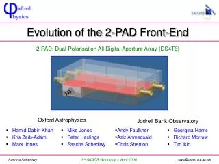
Oxford Astrophysics. Jodrell Bank Observatory. Hamid Dabiri Khah Kris Zarb-Adami Mark Jones. Mike Jones Peter Hastings Sascha Schediwy. Andy Faulkner Aziz Ahmedsaid Chris Shenton. Georgina Harris Richard Morrow Tim Ikin. Evolution of the 2-PAD Front-End.

E N D
Oxford Astrophysics Jodrell Bank Observatory • Hamid Dabiri Khah • Kris Zarb-Adami • Mark Jones • Mike Jones • Peter Hastings • Sascha Schediwy • Andy Faulkner • Aziz Ahmedsaid • Chris Shenton • Georgina Harris • Richard Morrow • Tim Ikin Evolution of the 2-PAD Front-End 2-PAD: Dual-Polarisation All Digital Aperture Array (DS4T6) 3rd SKADS Workshop – April 2008
2-PAD Analogue Signal Path Bunker RFI Shield Custom Analog Chip Custom Digital Chip Ant. polarisation PCB Plug HSS interface 4 off Beamformer Processors Processor Switch Noise source 4-bit ADC PSU Beamformer Processor Beam combing Processor +ve Reg } 4 i/ps each ....... PCB Station processors Custom Analog Chip(s) ....... From other beamformer proc. Analog Twisted Pair PSU 4-bit ADC LNA 256 elements x2 polarisations 128 analog i/ps Digital beams out 4 i/ps each ... Total 512 inputs ... Analog sig. conditioning control Control Processor Line Tx/Rx Station Control Buffers Time standard 3rd SKADS Workshop – April 2008
Eventual Goal MMIC LNA 2-PAD Front-End Module Shielded Bunker Wall Front-End Module Line Driver LNA Amplification CoaxialCable TwisterPair ReceiverBoard Antenna Noise Diode Power Regulator 3rd SKADS Workshop – April 2008
Previous Front-End Prototypes Gain Chain v1 Gain Chain v3 Gain Chain v2 Several Issues Identified! 3rd SKADS Workshop – April 2008
Next Generation Front-End • Address identified issues, plus: • Dual-polarisation front-end module • Mass production plastic enclosure • Cheap metallisation of surfaces • Temperature stabilisation/cooling Still More Outstanding Issues! 3rd SKADS Workshop – April 2008
Antenna Specific LNAs Embrace Tile Oxford Log-Period Dipole Flowpad 3rd SKADS Workshop – April 2008
Output – Twisted Pair Cable • Coaxial cable problematic • Results in very high connector densities • Expensive • Twisted pair (CAT7) • Cheaper and more channels per area • Requires differential output 3rd SKADS Workshop – April 2008
Current Front-End Version Antenna Specific LNA Quad Channel Amplifier Box Coax / Semi Rigid (~1m) CAT7(~20m) Amp2 Balun SMA Amp1 Amp3 TERA LNA Amp? SMA SMA 3rd SKADS Workshop – April 2008
Conclusion and Further Work • First revision of current version nearing completion • We will continue to evolve the 2-PAD front-end until it reaches the functionality appropriate for the SKA 3rd SKADS Workshop – April 2008
Gain Chain Versions 1 to 3 3rd SKADS Workshop – April 2008
Gain Chain Version 4 Design • Commercial Front-end Module • http://www.nuwaves-ltd.com/pdf/uHILNA%20Data%20Sheet.pdf 3rd SKADS Workshop – April 2008
Oxford Log-Periodic Dipole • Physical Properties • beam width: 22° (HPHW) • forward gain: 11.5dBi • low horizon side lobes • frequency range: 0.3-1.0GHz • return loss: better than −15dB 3rd SKADS Workshop – April 2008
Oxford Log-Periodic Dipole forward gain simulation limitation cross-polarisation • Physical Properties • beam width: 22° (HPHW) • forward gain: 11.5dBi • low horizon side lobes • frequency range: 0.3-1.0GHz • return loss: better than −15dB 3rd SKADS Workshop – April 2008
Complete Test Chain • Commercial LNA • (for testing this antenna only) Amplifier Box SignalConditioningModule 3rd SKADS Workshop – April 2008