Download
1 / 55
550 likes | 796 Views
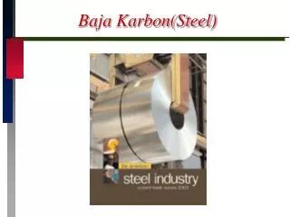
Mission :BAJA SAE ASIA 2010 Team : BLACK MAMBA Institute: NIT Rourkela, Orissa. Visit us at : www.saenitr.in. Material & Roll Cage Analysis. Material of Chassis Tube Size: Outer diameter=1 inch. , Inner diameter=0.74 inch. Approx. Length Required: 150 ft

E N D
Mission :BAJA SAE ASIA 2010 Team : BLACK MAMBA Institute: NIT Rourkela, Orissa Visit us at : www.saenitr.in
Material of Chassis • Tube Size: • Outer diameter=1 inch. , Inner diameter=0.74 inch. • Approx. Length Required: 150 ft • Material selected: • 1018 carbon steel because of following reasons: • High tensile strength. • Good weldability. • Low cost. • Availability Visit us at : www.saenitr.in
Material Composition Visit us at : www.saenitr.in
Mechanical Properties: Visit us at : www.saenitr.in
Weldability A measure of whether a steel can be easily welded is to determine the carbon equivalent (Cequiv) of the steel. For 1018 Carbon Steel : Cequiv=0.2+(0.9/6)=0.35 (Easily weldable) Cr+Mo+V Mn Ni+Cu + Cequiv C + + = 6 5 15 Visit us at : www.saenitr.in
Rollcage With Dimension Visit us at : www.saenitr.in
Welding Process Tungsten Inert Gas (TIG) welding is preferred for welding the parts of rollcage. • The TIG (Tungsten Inert Gas) welding process generates heat from an electric arc maintained between a non consumable tungsten electrode and the part being welded. • Gas is fed through the torch to shield the electrode and molten weld pool to prevent oxidization. • Filler rod , same as that of base metal is added to the weld pool separately. Visit us at : www.saenitr.in
TIG Welding Benefits • Superior quality welds • Welds can be made with or without filler metal • Precise control of welding variables (heat) • Free of spatter • Low distortion Visit us at : www.saenitr.in
Ansys Report The vehicle collides with a rigid wall at 60kmph (sixty kilometers per hour) and comes to a standstill in 0.2 seconds. We analyze the impact from four directions. This value of deceleration coupled with the full loaded mass of the vehicle which is approximately 350 kg (three hundred fifty kilograms) amounts to forces of approximately 29 kN (twenty nine kilo Newton). The calculations are as follows : acceleration in meters per second squared=(60)*(5/18)*(1/0.2) =83.33 Force is mass times acceleration. So force in Newton =350X83.33 =29166N ~29kN Visit us at : www.saenitr.in
Front Impact • The load is applied on the two horizontal front extremity members while keeping the rear plane fixed .Each force is having a magnitude of 14.9kN and directed inwards along the X-axis. The massive force no doubt bends the bars substantially, but it doesn’t deform the driver’s compartment much. Max Stress= 4.56 x 10⁸ pa. Min Stress= 0 Visit us at : www.saenitr.in
Side Impact • A sideways impact is on that poses maximum threat to the driver’s safety. This has the potential tendency of crushing the compartment space. We have applied a load of 29 kN at the side bracing upper member while keeping the other side fixed. Once again no doubt the deformation is present but the driver has a good chance of staying unhurt. Max Stress= 2.64 x 10⁹ pa. Min Stress= 0 Visit us at : www.saenitr.in
Rear Impact • Similar to the front impact case, here also we have two 14.5 kN forces doing the damage. The forces are applied on the horizontal members inwards along the X-axis while the front extremity plane is kept fixed at its position. This does much less deformation because of the extensive frame work at the drivers back resting plane. Max Stress= 9.21 x 10⁸ pa. Min stress= 0 Visit us at : www.saenitr.in
Roll Over • The applied load for analysis is 3500N. From the Von-Mises diagrams we see that the long and mostly unsupported member has bent quite some amount but not enough to render the driver hurt. So all the analysis confirm the safety of the rollcage. The material employed for analysis is structural steel but the one to be employed for actual fabrication is the much tougher and lighter alloy steel which thus guarantees better results. Max Stress= 2.36 x 10⁸ pa. Min stress= 0 Visit us at : www.saenitr.in
Engine & Transmission Visit us at : www.saenitr.in
Engine Mounting FRONT This is how a Greaves engine is conventionally mounted along with the transmission in a Alfa vehicle. This brings the CG towards the rear. Visit us at : www.saenitr.in
Engine Alignment Side View FRONT Visit us at : www.saenitr.in
Schematic Of Engine And Transmission Meshing We plan to flip the transmission 180° about the vertical plane. This arrangement brings the CG much inwards towards the centre of the vehicle FRONT Visit us at : www.saenitr.in
Allied Systems(fuel Feed Pump) • Use of feed pump allows fuel tank to be placed in a lower level. • Allows easier and better safety during fuel filling operation. Visit us at : www.saenitr.in
Splash Shield The use of a well designed splash shield ensures better safety. We intend to use threaded fixtures for fitting petroleum insoluble plastic tubes for drainage and with appropriate ID for negligible constriction. We further dampen the probability of fuel deposition by having provision of 3 drainage lines. Visit us at : www.saenitr.in
Overspeeding Limiter Arrangement Tachometer Micro controller Ignition coil Relay To distributor Visit us at : www.saenitr.in
Overspeeding Limiter Arrangement When the speed of the vehicle reaches 60km/hr, the microcontroller detects the reading and sends the signal to the relay so that the connection to the ignition coil breaks and hence the engine misses some sparks and hence the speed of the engine decreases. Visit us at : www.saenitr.in
Transmission • We intend to use the transmission of Mahindra Alfa as it best matches the engine characteristics of the Lombardini LGA 340 Visit us at : www.saenitr.in
Half shafts assembly The part fitted with the differential is of Alfa and that with the wheels is of Maruti 800. we have used press fit with external sleeve for the attachment and finally welded (shown in green) Visit us at : www.saenitr.in
A Closer Look The ends of the half shaft are attached by means of CV(constant velocity) joints Visit us at : www.saenitr.in
Calculation Max. Torque = 19 Nm @ 3000 rpm For 1st Gear (gear ratio = 31.48 : 1) Torque = 19 * 31.48 = 598.12 Nm Wheel Diameter = 21” Force = 598.12/0.2667 = 2242.67 N Mass of the vehicle (including driver) = 350 kg (approx.) Acceleration = 2242.67/350 = 6.4m/s2 Co-efficient of friction = 2242.67/(350 * 9.81) = 0.65 (min.) The value of Co-efficient of friction should be at least 0.65 for an acceleration of 6.4m/s2 Visit us at : www.saenitr.in
Shift By Wire Design Schematics There are two paddle shifts provided for up shift and down shift. Pulling the pedal up changes the gears. Micro controller Upshift Downshift Visit us at : www.saenitr.in
Schematic Of The Arrangement At The Gearbox End 1 2 3 4 The pulley is used for the conventional sequential shift. The dog teeth helps to engage the shifter motor of the shift-by-wire system. To micro controller +5V Visit us at : www.saenitr.in
Schematic Of The Arrangement At The Gearbox End • The Slip ring mechanism keeps the pulley at +5V. The contact pin makes contact with the points when engaged at that particular gear. • These connect to lines that go to the microcontroller that drives the shifter motor accordingly. • For example , let us consider the vehicle is engaged in 2nd gear. If we intend to shift to 3rd gear, we pull the up shift lever , this sends a signal to the microcontroller. • The sequence of operations are : engage solenoid, turn motor in a direction to up shift ,turn till signal from 3rd gear contact is received, stop rotation, disengage solenoid • This system ensures that in case of a failure, the driver can easily get hold by the conventional gear shift stick without the need of any mode conversion intervention. Visit us at : www.saenitr.in
Schematic Of Solenoid Engager/ Dis-engager And Shifter Motor From driver chip From driver chip Solenoid Dogteeth Internal Spline Shifter motor Visit us at : www.saenitr.in
Suspension & Steering Visit us at : www.saenitr.in
Basic Suspension System The primary purpose of a suspension system is to support the weight of the vehicle and give a smooth ride. It is desirable that it should also: • allow rapid cornering without body roll when the car leans to one side. • keep tires in firm contact with the road at all times and conditions. • prevent body squat (tilting down at rear) when accelerating. • prevent body dive (tilting down at front) when braking. • allow front wheels to turn for steering. • keep the wheels vertical and in correct alignment at all times. • Suspension travel length = 8.5”, taking stiffness constant, • k = 1800 kg/m Visit us at : www.saenitr.in
Double Wishbone Suspension • Double wishbone suspension is an independent suspension design using two parallel wishbone-shaped arms to locate the wheel. • Each wishbone (or arm) has two mounting positions and attached to the knuckle via ball joints. • The shock absorber and coil spring mount to the wishbones to control vertical movement. • Double-wishbone designs allow to control the motion of the wheel throughout suspension travel, controlling such parameters as camber angle, caster angle, toe pattern, roll center height, scrub radius, scuff and many more. Visit us at : www.saenitr.in
Why Double Wishbone ? • It is fairly easy to work out the effect of moving each joint, so one can tune the kinematics of the suspension easily and optimize wheel motion. • It decreases the cambering effect. • It checks the body vibrations. • Material to be used: MS tube • Outer Diameter : 1” • Wall Thickness : 0.2” Visit us at : www.saenitr.in
Ackermann Steering Geometry • The steering arm makes 74° with the axis parallel to wheel axis . It is calculated by the formula • tanθ=wheel base/ (track width/2) Or,θ=74° Visit us at : www.saenitr.in
Roll center The roll center is the point about which the vehicle rolls when cornering and is different for front and rear part. The front roll centre is usually lower than the rear, thereby transferring weight to the rear during cornering. In our design we have parallel wishbone system which results in the roll center appearing very near to the ground which is beneficial for stability during cornering. Visit us at : www.saenitr.in
Track rod length=62-(2*14.61)-(2*8)=16.78 inch • Track rod offset from center of wheels=3*sin74° ,where 74° is the Ackerman angle. • Tie-rod length=14.32-(3*cos74°)=13.49 inch{Taking length of steering arm=3 inch making 74° with axle} • Calculation of scrub radius: • Caster trail=10.5*tan10°=1.85 inch • Due to KPI of 10°, shift = 10.5*sec 10°*tan 10° =1.88 inch • Scrub radius=2.81 inch Zoom view Caster trail Visit us at : www.saenitr.in
It consists of steering wheel , steering shaft , rack and pinion gear box with gear ratio 18:1. • Selected over recirculating ball steering system for its lesser complexity of design. Visit us at : www.saenitr.in
Design calculation FOR THE DESIGN OF AXLES AND TIE ROD WE WILL USE MILD STEEL AND THE ENTIRE CALCULATION IS BASED ON THE FOLLOWING DATA: Material Property Magnitude Modulus of Elasticity 200GPa Tensile Strength 455MPa Yield Strength (tension) 250MPa Poisson's Ratio 0.29 The maximum weight of the vehicle as per the specification is: 330Kg. Taking factor of safety into account while design let the load be: 350Kg. The aim is for the car to weigh approximately 350 kilograms and it is expected to generate about one times the force of gravity in cornering. As stated previously these forces were increased to give a suitable factor of safety. It was determined that a cornering force of two times the force of gravity and a weight force of 350 kilograms would be suitable. After applying the weight force in the centre of the tyre and the cornering force across the tread surface of the tyre, and working out the moments around the wheel bearing centres, it was possible to work out the forces on the top and bottom suspension mounting points to be approximately 3500N and 10500N …..(3500+3500*2) respectively. STEERING RATIO: It is defined as the angle made by the steering wheel for each 1deg movement of wheel. It has been found that car requires 580deg of steer wheel for 35deg movement of wheel .Thus the steering ratio is: 580/35 or 16.5:1. It should be within 12 to 20 .So the design is safe. Minimum Turn Radius Track (T)= 48 inch WHEEL BASE (W)=87 inch θ=35deg. R1= T/2 + W/sin θ =175.68 inch=446.23 cm=4.5m(approx) Visit us at : www.saenitr.in
Determining the rack load R = steering wheel radius = 300mm r = pinion pitch circle radius = 5 mm T = number of pinion teeth = 5 P = linear or circular pitch = 2π r/t = 6.28 mm E = input steering effort = 2*20 = 40N W = output rack load If the pinion makes one revolution; input steering wheel movement, Xi = 2 π R output rack movement ,Xo = 2π r movement ratio(MR) = 2πR/(2π r)= R/r=60. Assuming no friction: MR = W/E. W = E*MR = 40*60 = 2400 N. Visit us at : www.saenitr.in
Shear stress through the bolt for the bottom spherical rod end. F = 10500N (as found previously for the bottom of the front upright); d = 10mm (diameter); Area of the bolt, A = π d2/4 = 78.5mm2. Shear stress in the bolt, σ = F/A = 10500/78.5 = 133.76MPa. This is much lower than the maximum permissible shear stress(250MPa) for high tensile steel. Stress in the tie-rods.( data taken from Maruti Alto) W = 2400N (as found previously for the rack output load); d = 15mm (inside diameter of tie-rod); D = 18mm (outside diameter of tie-rod); L = 337mm (length); FOS = 2 (factor of safety) E = 200GPa (modulus of elasticity). Visit us at : www.saenitr.in
From Euler's formula: W = π2 *EI/L2 I = FOS*W*L2/( π2 * E) = 2.76*10-10 m4 Also I = π( D4-d4)/ 64 = 2.76*10-10 m4 Putting d = 15mm we get Dmin = 4√56251.09 = 15.4004 mm But we have D= 18 mm .Thus our design is safe. Stress at the base of front upright F = 10500N (as found previously for the bottom of the front upright); L = 89mm (length); D = 40mm (outer diameter); d = 30mm (inner diameter); and y = 20mm (centroid). Moment about the base of the upright, M = F * L = 10500 * 89 = 934500 Nmm Second moment of inertia, I= π( D4- d4)/64 =85902.9 mm4. Find the stress at the base of the upright: σ=M*y/I = 934500*20/85902.9= 217.57 MPa. This value is lower than the 250MPa . So the design is safe. Visit us at : www.saenitr.in
Braking System & Tyres Visit us at : www.saenitr.in
Brake Pedal Fulcrum • Brake pedal defined as the ratio = B/A • The Brake pedal ratio used in our vehicle is 6.2:1 (since not using vacuum booster) • The length of the brake pedal is B=216mm and the distance of the point of attachment from the fulcrum i.e. A=36mm. Point of attachment A Output: force applied to the piston of master cylinder B Input: force applied by the driver Visit us at : www.saenitr.in
Master Cylinder & Reservoir The master cylinder used by us is 19.05mm/(3/4inch) tandem master cylinder. The reservoir used is of Maruti Swift Dimensions : 100mm * 30mm * 50mm (L*B*H) Brake Oil used is DOT 5 Visit us at : www.saenitr.in
Brake Lines • Consists of Steel pipe and Hose pipe • Steel pipe running over chassis • Hose pipe running from chassis to disc brakes Steel pipe = double wall steel tubing (Bundy tubing) of outer diameter 3/16 inch. Hose pipe = 10mm (outer diameter) Steel pipes Hose pipe Visit us at : www.saenitr.in
Disc Brakes & Parking Brakes • Disc Brakes used in all 4 wheels • Disc Brakes of Maruti 800 in the front and rear with an additional caliper of BAJAJ Pulsar on each rear wheel for hand operated parking brake and closely placed individual parking brake levers which can be used together for normal parking or individually for differential braking for coming out of situations where a single wheel is stuck. • Proportioning Valve provided at the front brakes Visit us at : www.saenitr.in
Primary System Secondary System Front Axle Rear Axle Hydraulic System Configuration The hydraulic system used is front/rear hydraulic split system Advantage In case of a leak/failure at any point in the system, effective braking power will be maintained on at least two wheels. Visit us at : www.saenitr.in
Brake Lights & Ergonomics • Equipped with two(2) brake lights with independent circuitry, which meets SAE/AIS/ISI rated • The Brake pedal will be mounted such that the leg ankle makes a optimum 90° during off position (pedal) and maximum 125° during full on position (pedal) (to avoid pain in toe extensor muscles) Visit us at : www.saenitr.in
TYRES • All four tyres of same dimensions • Used ATV tyres • Specification • Diameter : 21 inch • Rim Diameter :10 inch • Tread width : 8 inch Visit us at : www.saenitr.in


![NATIONAL RURAL LIVELIHOODS MISSION [NRLM]](https://cdn0.slideserve.com/652488/slide1-dt.jpg)