Download
1 / 22
220 likes | 459 Views
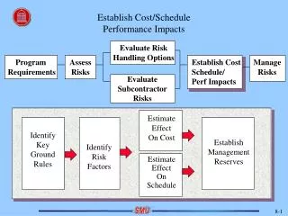
New Low Cost & High Performance Transmission Line. Eun Sub Shim Micro/Nano Systems & Controls Lab. SNU. 2004. 6. 21. Contents. Introduction Survey HRS t-lines LRS t-lines Best Performances New Design Design Consideration Wet-etched CPW Structure Process Properties Conclusion

E N D
New Low Cost & High Performance Transmission Line Eun Sub Shim Micro/Nano Systems & Controls Lab. SNU 2004. 6. 21
Contents • Introduction • Survey • HRS t-lines • LRS t-lines • Best Performances • New Design • Design Consideration • Wet-etched CPW • Structure • Process • Properties • Conclusion • References
Michigan Microstrip (1993-1998) HRS [1] • SMM (shielded membrane microstrip) • Advantage • No dielectric loss • Self-packaging • Loss: < 0.6 dB/cm @ ~110 GHz • HRS • SiO2/Si3N4/SiO2, 1.5 µm • Metal: Ti/Au, 1.2 µm • Selective etching: EDP • Bonding: conductive epoxy
Michigan CPW (1998-2002) HRS [2] • Membrane CPW • MFGC (micromachined finite ground CPW) • Advantage • Reduce dielectric loss • Simple process • Loss: 0.5 dB/cm @ 40 GHz • HRS • SiO2/Si3N4/SiO2, 1.5 µm • Selective etching: EDP • Metal: Cr/Au, 1.7 - 2 µm
GEC Marconi Instrument CPW (1998) HRS [3] • Trenched CPW • Loss: 1.8 dB/cm @ 40 GHz • 650 µm-thick 10000 Ohm-cm HRS • Metal: Al evaporation 1.46 µm • CF4 plasma etch
SNU CPW (2000) HRS [4] • ECPW (elevated), OCPW (overay) • Loss: 1 dB/cm @ 40 GHz • Glass substrate • Metal1: Ti/Au electroplate 3 µm • Metal2: Cr/Au electroplate 3 µm • Thick PR(AZ 4620): 15 µm • PR Curing: 200oC
LAAS-CNRS CPW (1997, 2003) LRS Metal BCB Si [5] • CPW on Membrane • Loss: 1 dB for 2,4,6 mm @ 40 GHz • Access port loss is dominant • 20 Ohm-cm silicon (350 µm) • SiO2/Si3N4, 1.4 µm (0.8/0.6) • Metal: 2.5 µm • Silicon etch: KOH • CPW on BCB • Loss: 4.6 dB/cm @ 40 GHz • 20 Ohm/cm silicon • Deep RIE : 10 µm • BCB: 10 µm • Metal: Ti/Au, 3 µm
NIST CPW (1997) LRS [6] • Circuit: foundry survice (Magic) • Glass with etch hole • 0.6 µm-thick Al pattern in glass • 460 µm-thick silicon • Hybrid etch process • Isotropic etch: XeF2 (16 min) • Anisotropic etch: EDP (1h 92o) • Loss:4 dB/cm @ 40 GHz
KAIST air gap lines (2002) LRS [7] • Ground electroplating + LIGA x 4 • Ti/Cu electroplating, 12 µm • Thick Oxidized Porous Silicon (OPS) • 10 Ohm-cm silicon substrate • Oxide thickness: 20 µm • Air gap CPW • Loss: 0.7 dB/cm @ 40 GHz
KAIST CPW (2003) LRS [8] • Thick Oxidized Silicon • Oxide thickness: 7 µm • Conductivity: 10 Ohm-cm • Ground electroplating + LIGA x 2 • PR1: AZ 9260 (10 µm) • PR2: ? • Ti/Cu electroplating, 10 µm • Thick Oxidized Porous Silicon • Loss: 0.35 dB/cm @ 25 GHz
SNU Thin Film Microstrip (TFMS) line [9] • MMIC 설계에 필요한 집중소자를 BCB위에 제작하여 signal과 같은 상에 위치시키는 구조 제안 • BCB 식각시 PR mask 사용 • 능동소자를 signal과 같은 위치에 놓기 위하여 기판을 깎아서 ground를 낮게 형성함 • TFR과 capacitor를 signal과 같은 위치에 형성함 • TFMS line loss • 0.26 dB/mm @ 50 GHz
Best Performance • HRS • Michigan (1993-1998) • Loss: < 0.6 dB/cm @ ~110 GHz • Three HRS substrates • Bonding alignment • Back side process • LRS • KAIST (2003) • Loss: 0.35 dB/cm @ 25 GHz • Complicated process Cheap & simple process
Design Consideration • Substrate coupling • Isolating transmission line from substrate • Field out of substrate • Leakage current path • Trench, air gap • Metal loss • Smooth metal surface, Thick metal line • Electroplating vs. Sputtering • Transition • Conventional T-line to New T-line ? OLD NEW
Wet-etched CPW Zo=49 Ohm Loss= 0.57 dB/cm @ 40 GHz
Structure Silicon Metal • Minimize substrate coupling • No leakage current path • Rigid structure (thick metal) • Smooth metal surface • Simple process 10 um 100 um 100 um 71 um 54.7o 280 um
Process 1. Photolithography 4. CMP Silicon PR Metal 5. TMAH etch 2. KOH etch 3. Electroplating Single mask process!! Cheap & Simple Process!!
Attenuation • Attenuation • 0.21 dB/cm @ 20 GHz • 0.57 dB/cm @ 40 GHz • 1.19 dB/cm @ <100 GHz
Attenuation • KAIST CPW paper (20 GHz) • Fabricated: 0.35 dB/cm • Simulation: 0.22 dB/cm • KAIST CPW simulation • Loss: 0.34 dB/cm @ 40 GHz • Wet-etched CPW simulation • 0.21 dB/cm @ 20 GHz • 0.57 dB/cm @ 40 GHz • Comparable to world’s best CPWs GEC Marconi HRS (1998) Michigan HRS (2002) KAIST LRS (2003) 0.2 This work LRS
Rigid structure • Other CPWs • Membrane type : Michigan, LAAS-CNRS, NIST • SiO2/Si3N4 membrane (t<1.5 µm) • Suspended metal : KAIST • Cu (t=10 µm, w=100 µm) • Wet-etched CPW • Suspended Metal bar • Cu (tmax= 71 µm, w=100 µm)
Simple process • Single mask process • No misalinement effect • Cheap process Cf. other lines • Membrane type : Michigan, LAAS-CNRS, NIST • Minimum 2 mask is needed • Suspended metal : KAIST • Minimum 3 mask is needed
Conclusion • CPW survey • HRS • Michigan (1993-1998) • Loss: < 0.6 dB/cm @ ~110 GHz • LRS • KAIST (2003) • Loss: 0.35 dB/cm @ 25 GHz Expensive & Complicated process • New Design: Wet-etched CPW • Low loss: 0.12 dB/cm @ 20 GHz, 1.19 dB/cm @ <100 GHz • Rigid structure • Single mask process Low cost & High performance CPW fabrication is possible!!!
References [1] L. P. B. Katehi, G. M. Rebeiz, T. M. Weller, R. F. Drayton, H. Cheng and J. F. Whitaker, “Micromachined Circuits for Millimeter- and Sub-millimeter-Wave Applications”, IEEE Antennas and Propagation Magazine, Vol. 35, No. 5, Oct. 1993. [2] K. J. Herrick, T. A. Schwarz, and L. P. B. Katehi, “Si-Micromachined Coplanar Waveguides for Use in High-Frequency Circuits”, IEEE Transactions on Microwave Theory and Techniques, Vol. 46, No. 6, June 1998. [3] S. Yang, Z. Hu, N. B. Buchanan, V. F. Fusco, J. A. C. Steward, Y. Wu, B. M. Armstrong, G. A. Armstrong, and H. S. Gamble, “Characteristics of Trenched Coplanar Waveguide for High-Registivity Si MMIC Applications”, IEEE Transactions on Microwave Theory and Techniques, Vol. 46, No. 5, June 1998. [4] J. Park, C. Baek, S. Jung, H. Kim, Y. Kwon and Y. Kim, “Novel Micromachined Coplanar waveguide Transmission Lines for Application in Millimeter-Wave Circuits”, Japanese Journal of Applied Physics, Vol. 39, No. 12B, Dec. 2000. [5] F. Bouchriha, K. Grenier, D. Dubuc, P. Pons, R. Plana, and J. Graffeuil, “Minimization of Phassive Circuits Losses realized on Low Resistivity Silicon Using Micro-Machining Techniques and Thick Polymer Layers”, 2003 IEEE MTT-S Digest., 2003. [6] V. Milanovic, M. Gaitan, E. D. Bowen, and M. E. Zaghloul, “Micromachined Microwave Transition Lines by Commercial CMOS Fabrication”, IEEE Transactions on Microwave Theory and Techniques, vol. 45, no. 5, May 1997 . [7] I. Jeong, S. Shin, J. Go, J. Lee, C. Nam, and D. Kim “High-Performance Air-Gap Transmission Lines and Inductors for Millimeter-Wave Applications”, IEEE Transactions on Microwave Theory and Techniques, vol. 50, no. 12, Dec. 2002. [8] E. Park, Y. Choi, B. Kim, J. Yoon, and E. Yoon, “A LOW LOSS TRANSMISSION LINE WITH SHIELDED GROUND”, IEEE The Sixteenth Annual International Conference on Micro Electro Mechanical Systems, 2003., Jan. 2003. [9] 송생섭, 노훈희, 서광석, “Structural improvement of Thin Film Microstrip line for MMIC applications using MCM-D”, 제 11회 한국 반도체 학술대회, Feb. 2004.