Download
1 / 63
730 likes | 1.03k Views
V.G. Dubrovskii St. Petersburg Academic University & Ioffe Physical Technical Institute RAS, St.-Petersburg, Russia. Modeling of semiconductor nanowires. Plan: Introduction Growth modeling Crystal structure of III-V nanowires Strain induced by lattice mismatch

E N D
V.G. Dubrovskii St. Petersburg Academic University& Ioffe Physical Technical Institute RAS, St.-Petersburg, Russia Modeling of semiconductor nanowires • Plan: • Introduction • Growth modeling • Crystal structure of III-V nanowires • Strain induced by lattice mismatch • Self-induced GaN nanowires • Self-regulated pulsed nucleation in VLS nanowires dubrovskii@mail.ioffe.ru Repino, 14 July 2013, Lecture # 2
Books Monograph “Theory of formation of epitaxial nanostructures” By V.G. Dubrovskii Moscow, Fizmatlit 2009 352 p. New book (2013): V.G. Dubrovskii “Nucleation theory and growth of nanostructures” Springer
Selected papers on NWs 4 13 5
8 12
Papers on nucleation theory Nucleation and growth: 3 Ostwald ripening: Linear peptide chains:
Modern NWs and their applications GaN/AlN, Ioffe & LPN CNRS GaAs, MBE, e-beam (Ioffe & LPN CNRS) InAs/InP, Lund U InAs, MOCVD, nanoimprint (Lund U) Nanosensors Nanophotonics Nanoelectronics
Modern nanowires and their importance Nano Lett. 10, 1529 (2010) Where is the killer application? • Nanowire based single cell endoscopy Exponential increase in the number of publications: Biological probe for endoscopy, spot delivery and sensing within a single living cell 2) Nanowires for direct solar to fuel conversion 3) Integrated nanophotonics 1 – solar cells, 2 – LEDs/lasers, 3 – nanoribbons, 4 – photonic bandgap NW arrays, 5 – sample analysis chambers, 7- photodetectors, - microfluidic systems 4) fundamental physics: growth and properties
Advantages of nanowire based optoelectronics • Easy to fabricate uniform arrays by organizing seeds before growth • Smallest LEDs / lasers of any kind (10s nm in diameter, a few microns in length) • (Potentially) high efficiency (electronic active medium and • optical waveguide being identical: large confinement factor) • Vertical cavity and surface emitting • Easy to realize single photon emission • Much less restricted by lattice mismatch => III-Vs on Si substrates, coherent strained heterostructures in NWs • Wurtzite phase of ZB III-Vs (C. Chang-Hasnain group, UC Berkeley APL 2007)
Au-assisted VLS growth: the first wires Au-assisted CVD of Si “whiskers” on Si(111) at T~1000 0C (Wagner & Ellis, 1964) Fundamental aspects of VLS growth: Givargizov, in “Highly anisotropic crystals”, 1975 Alloy at equilibrium with solid Liquid Vapor Au catalyst • Si is transferred from vapor to solid through liquid drop on the • wire top (Tm=363 0C) • Liquid drop acts as a chemical catalyst: pyrolysis rate > 0 at the drop surface and = 0 at the substrate surface • Simple phase diagram of Au-Si alloy: no Au in the wire? Si wires
Kinetic processes driving nanowire growth 1 – direct impingement 2 – desorption from the drop 3 – diffusion from the sidewalls 4 – desorption from the sidewalls 5 – diffusion from the substrate to the sidewalls, 6 – diffusion from the substrate to the drop 7 – surface nucleation Nucleation-mediated wire growth resulting in the vertical growth rate Supersaturation of gaseous phase to the solid (= to equilibrium alloy with concentration Ceq) Supersaturation of (liquid) alloy in the drop to the solid V.G.Dubrovskii et al., PRE 2004, PRB 2005, PRE 2006, PRB 2008, PRB 2009; PRB 2010, APL 2011 W.Seifert et al., JCG 272, 211 (2004), L.Schubert et al., APL 84, 4968 (2004)….
Model of diffusion-induced NW growth • Stationary growth with R = const • Direct impingement • Adatom diffusion, substrate and sidewalls • GT effect in the drop Surface adatoms (s): Sidewall adatoms (f): Four boundary conditions: ω = 1 in MOCVD and 1/π in MBE Constant concentration far away from the wire Continuity of chemical potential at the wire base Continuity of flux at the wire base Continuity of chemical potential at the wire top V.G.Dubrovskii et al., PRB 2005, 2009, PRE 2006
J α Surface adatoms Sidewall adatoms Sa Direct impingement, Surface growth β Growth kinetics Due to GT effect, coefficients A, B and C can be of either signs ! B=0, C=0 (no diffusion): dl/dh=A, Classical Givargizov-Chernov case Generally: DI growth:
Theoretical L(t) curves @ RGT=3.5 nm Au-assisted MBE of GaAs NWs L(t) curves are essentially non-linear !!! V.G. Dubrovskii et al., PRB 2009
Narrowing size distribution of <110> Ge NWs nm Initial stage: Infinite growth: Limited growth: Dubrovskii et al., PRL 2012
Role of surface energies in NW polytypism Hexagonal cross-section: 1-st approximation for lateral surface energy:
Surface energies: summary Surface energy ratio WZ to ZB Dubrovskii et al., PRB 2008; Phys. Solid State 2010
G2< G1 Role of nucleation F.Glas et al., Phys. Rev. Lett. 2007, V.G. Dubrovskii et al., PRB 2008, J. Johansson et al, Cryst. Growth & design 2009 … • At lower surface energy of NW sidewalls, WZ phase can form only when nucleation • takes place at the triple phase line (TL) • In a mononuclear mode, the structure is dictated by the monolayer island orientation Two conditions of WZ phase formation: • Condition for TL nucleation (straight sidewalls): LV surface energy should not be too high! • High enough supersaturation to create a • stacking fault Nucleation barriers
Theoretical conclusions • Surface energy of relevant WZ sidewalls is indeed lower than of ZB ones • TL nucleation can be suppressed by a lower surface energy catalyst • Structure retains to bulk ZB at large R because the ring of critical size dissapears (Dubrovskii et al., PRB 2008) Growth and phase diagrams: CUB – blue curves HEX – red curves 0.83 0.875 τ=0.95 0.91 GaAs, R=20 nm
Two step growth with temperature ramping • 1nm Au layer deposited on GaAs(111)B surface • Sample A grown at 6300C from the beginning => no NW growth • Growth at 5300C for tLT; growth temperature ramped from 530 to 6300C within 2 min, Ga and As4 fluxes maintained; growth at 6300C, V=0.2 nm/s • Sample B: tLT=1.5 min, NO NW growth • Sample C: tLT=15 min, NW GROW longer than 2 nm V.G. Dubrovskii et al., PRB 2009 Riber 32 (LPN) Complex NW shape: Branching, tapering Continuing growth Sample A: tLT=0 Sample B: tLT=1.5 min Sample C: tLT=15 min
Two step growth with temperature ramping • - 0.4 nm Au layer deposited on GaAs(111)B surface • - Samples 1 grown at 6300 C from the beginning => no NW growth • Growth at 5500 C with V=0.3 nm/s for tLT • - Growth temperature ramped from 530 to 630 0C, • - Growth at 6300 C for 48 min, V=0.15 nm/s, V/III=4. • Sample 2: tLT =2 min, NO NW growth - • Sample 3: tLT =12 min, NW GROW longer than 10 microns EP1203 (Ioffe) More regular shape Sample 3 before and after high temperature growth step
Control of crystal structure: stacking fault free GaAs NWs grown with two T steps via scenario IV High resolution TEM studies of a NW detached from sample C: 200 nm 40 nm Pure WZ Pure ZB Transition region
Optical properties of WZ and WZ/ZB GaAs NWs: Pure WZ NWs B.V. Novikov et al., PSS RRL 2010: WZ/ZB heterostructures D. Spikoska et al., PRB 2009: Type II band structure: Predominantly ZB NWs Pure WZ NWs Band alignment and the first e and h levels v thickness PL spectra: 1.51 to 1.43 eV shift for different proportions of WZ EZB-EWZ=41 meV, redshift opposite to InP
Control of crystal phase by growth catalyst: Ga-catalyzed GaAs NWs Dubrovskii et al., PRB 2010, Nano Letters 2011 TPL nucleation condition: 1.3 J/m2 J/m2 J/m2 for Au-Ga (at 40% Ga percentage) = -0.23 to -0.11 J/m2 for contact angles from 110 to 1250 For pure liquid Ga at the growth temperature: A=drop B=WZ C=WZ-ZB mix-up D=ZB all the way 0.08 to 0.16 J/m2 =
Strain relaxation and critical dimensionsin freestanding nanowires • Because of free lateral surfaces • strain relaxation is expected to be • much more efficient • than in 2D layers and even QDs • Model • - linear isotropic elasticity • - same elastic parameters E, n Barton J. Appl. Mech. (1941) Elastic modulus Poisson ratio
ezz /e0 axis outer surface Strain maps E = 90 GPa, ε0 = 0.46, ν = 0.3
Heterostructured nanowires (QDs in NW) Axial or radial heterostructures Because of free lateral surfaces strain relaxation much more efficient than in 2D layers and even QDs !!! InAs QDs in InP NWs: Lund University
Relaxation of elastic stress in NS grown on a lattice mismatched substrate: existing models Major asymptotic properties: Simple: Elastic energy of 2D layer (per atom) Ratsch-Zangwill: Aspect ratio: Glas: Gill-Cocks:
Results for elastic energy relaxation Elastic constants of a cubic material Solid lines – calculations for different geometries Dashed lines - fits Relative strain energy for cylinders 5.5 (cone), 8 (truncated cone 700), 15 (cylinder) and 50 (reverse cone 1100)
z r h 2R Critical thickness for plastic relaxation Energy per of a dislocation pair (Glas, PRB 2007): if if b is the core cutoff parameter for elastic stress, θ is the angle between the Burgers vector and dislocation line Elastic energy: a = 1 for cylinder and 0 for cone
Critical thickness for plastic relaxation The excess energy of dislocation pair with respect to a fully coherent state is: Pure edge dislocations: 600 dislocations: Coherent state is stable Dislocations Critical thickness for dislocation formation
Critical thickness for plastic relaxation 600 dislocations in cylinder geometry: Critical thickness tends to infinity at certain critical radius which depends on lattice mismatch and NS geometry! 4% - GaAs/Si, 8.1% - InP/Si, 11.6% - InAs/Si
Critical dimension for plastic deformation at , therefore the equation for critical dimension is given by Critical radius v mismatch for different geometries: Dots showing MOCVD and MBE experimental data
III-V NWs on Si substrates: MOCVD a – InAs with 20 nm Au on Si(111) b – InP with 20 nm Au c – InP with 60 nm Au d – InP with 120 nm Au e – TEM of 17 nm diameter InAs NW Critical diameter for the growth of epitaxial NWs on the lattice mismatched substrates (C. Chang-Hasnain group, APL 2007) WZ phase !!!
III-V NWs on Si substrates: MBE Cirlin et al., PSS RRL 2010
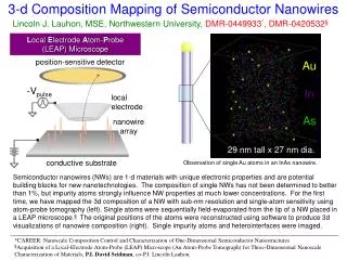
Problems with VLS nanowires • Unwanted Au contamination • Uncontrolled zincblende-wurtzite polytypism Use catalyst-free NN formation (GaAs on Si or sapphire) Use self-catalyzed growth (Ga instead of Au in the case of GaAs NWs) Au distribution in Au-seeded Si NWs (by P. Pareige, Rouen University, France)
Au contamination of Si and Ge NWs grown by MBE Nanoscale RL
Self-induced GaN NWs on Si: new growth mechanism • No Ga drops are detected on top => not VLS mechanism • GaN never nucleates as NW, nanoislands of different shapes are • formed in the beginning (different shapes on an amorphous SixN • interlayer or on mismatching AlN layer) • Even on AlN, misfit dislocations are formed before NW formation; NWs • are relaxed from the very beginning • MBE of self-induced GaN NWs employs specific growth conditions: • high N flux and high temperature are required • Surface diffusion plays a crucial role in NW growth • GaN NWs usually grow in both vertical and radial directions • GaN NWs are hexahedral, restricted by 6 equivalent low energy m-planes
Self-induced GaN NWs on Si(111): radial growth ! Histograms showing diameter distributions: Growth mechanism: Length-diameter dependence: • No drops are seen on NW tops • NWs growing in vertical and radial direction
Nucleation on lattice mismatched AlN layer • MBE on Si(111) substrates • 5 nm thick AlN buffer layer • GaN growth at T=800 C, N/Ga fluxes ratio =10 HR TEM images: RHEED patterns: 2 min, AlN buffer 10 min, GaN islands 17 min, GaN NWs RHEED and HRTEM studies show misfit dislocations in islands! a – SC islands; b – truncated pyramids c – full pyramids, d – NWs, island to NW transition at ~ 13-14 nm radius
Role of misfit dislocations Height v radius for different structures: dislocation
GaN NWs are relaxed from the beginning! Model suggesting a series of shape transformations to relax elastic stress, NW is already relaxed: Plastic relaxation in islands is also shown in: O. Landre, C. Bougerol, H. Renevier, and B. Daudin. Nanotechnology 20, 415602 (2009)
Nucleation on an amorphous interlayer • Si(111) substrate • 5 min exposure to active N to form SixNy amorphous layer • GaN growth at T=780 C, N/Ga fluxes ratio =6.2 • Epitaxial constraint should be weak! HR TEM: RHEED patterns: r0=5 nm Transition Incubation SC NWs
Scaling model for nucleation and growth of GaN NWs J. Tersoff, R.M. Tromp, Phys. Rev. Lett. 70, 2782 (1993) • Assumptions: • No strain-induced contributions, directly applicable on an amorphous interlayer • Anisotropy of surface (and edge) energy as the dominant driving force • Growth anisotropy: superlinear length-radius dependence of GaN NWs ! • Compare surface energy of isotropic island and anisotropic NW at given volume Illustration of the model: Surface energy of isotropic island: In SC geometry: Island volume: In SC geometry: NW volume: Surface energy of NW:
Scaling model for h(r) Superlinear dependence of NW length on radius with a>1 for all t With this dependence, from Using this in previous equations, the driving force for island to NW shape transformation is obtained in the form edges sidewalls in-plane Results of statistical analysis of TEM and SEM data remarkably follows the scaling dependence at: and
General condition for anisotropic growth NW anisotropic growth is energetically preferred NW growth is suppressed between No edge contributions where are positive roots of cubic equation Interesting NW case relates to NW sidewall energy should be much smaller and in-plane energy compared to surface energy of the island ! 0.088
Parameters of GaN spherical caps and NWs Boxy hexahedral islands with constant aspect ratio h/r = 0.088 5 nm from experimental data 3.4 nm from growth law In view of small prefactor and larger contact angle of NWs 130 meV/A2 known 137 meV/A2 Assume 100 meV/A2 meV/A2 (was 40 meV/A2 by analogy with Si/SiO2) 230 meV/A2 (was 130-176 meV/A2 from Young’s eq.) 0.088
Elongation: Tip SW surface Top facet Scaling in GaN NW growth: kinetic model Radial growth: Schematics of possible growth scenarios: Yellow – NW surface contributing to elongation Magenta – desorption area Grey – NW surface contributing to radial growth Blue – overgrown shells SW collection a – no radial growth, R=const b – R~t c – tapered shape d – cylindrical shape, SCALING! Neglect c, adopt model d with
Scaling in GaN NW growth: L(t), R(t) V=0.045 nm/s; a=65 nm R(t0)=17 nm, L(t0)= 140 nm d=2.46: Condition for super-linear NW growth: