Download
1 / 14
140 likes | 207 Views
Electronic Properties of Si Nanowires. Yun Zheng, 1 Cristian Rivas, Roger Lake, Khairul Alam, 2 Timothy Boykin, and 3 Gerhard Klimeck Deptartment of Electrical Engineering, University of California Riverside 1 Eric Jonson School of Engineering, University of Texas at Dallas

E N D
Electronic Properties of Si Nanowires Yun Zheng, 1Cristian Rivas, Roger Lake, Khairul Alam, 2Timothy Boykin, and 3Gerhard Klimeck Deptartment of Electrical Engineering, University of California Riverside 1Eric Jonson School of Engineering, University of Texas at Dallas 2University of Alabama Huntsville 3Department of Electrical and Computer Engineering, Purdue University
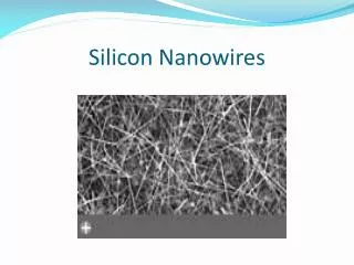
Si [100] Nanowire Structure Unit Cell H passivated Si Nanowire on Si substrate
Approach R gs L gs L R G1,1 = [E – D1 – t1,0 gs t0,1 – t1,2 g2,2 t2,1 ]-1 R R gi,i = [E –Di – ti,i+1 gi+1,i+1 ti+1,i ]-1 • sp3s*d5 empirical tight binding model • parameters optimized with genetic algorithm (Boykin et al., Phys. Rev. B, v. 69, 115201 (2004). • 3D discretized effective mass model • E – kz (zeegv) • Transmission vs. E • NEGF and RGF T = tr{G1,1[ A1,1 - G1,1G1,1G1,1]} R R† R
Splitting of X4 States at G The lowest state is the reference energy E=0 at each dimension.
Splitting of 3 Highest Valence Bands at G The highest state is the reference energy E=0 at each dimension.
Effective Mass at Conduction Band Edge Bulk mt = 0.2 m0 0.27 m0
Effective Mass at Valence Band Edge • [100] bulk masses: mhh = 0.28 m0, mlh = 0.21 m0, and mso = 0.25 m0
Conduction Band Transmission: Full Band and Single Band T = tr{G1,1[ A1,1 - G1,1G1,1G1,1]} • 1.54 nm Si wire. • Band edges differ by 100 meV.
Valence Band Transmission: Full Band and Single Band • Band edges differ by 18 meV. 1.54 nm wire
Conclusion • Brillouin zone ½ length of bulk Si along D line. • Conduction band: Valley splitting reduces m* and confinement increases mt of bandedge (34% for 2.7nm wire). • m* of valence band edge 6x heavier than bulk and next highest band even heavier. • For wires > 1.54 nm, conduction band edge splits into 3 energies. Center energy is 2-fold degenerate evenly spaced between lowest and highest energy. Band-edge is non-degenerate.