Download
1 / 17
170 likes | 312 Views
LINAC4 – LBS & LBE Lines dump design. F. Regis, 07-04-2011. Outline. LBS and LBE lines Design specifications Dump features LBS dump: RP preliminary analysis General design features Energy deposition Thermal analysis Structural analysis Conclusions and next steps

E N D
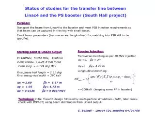
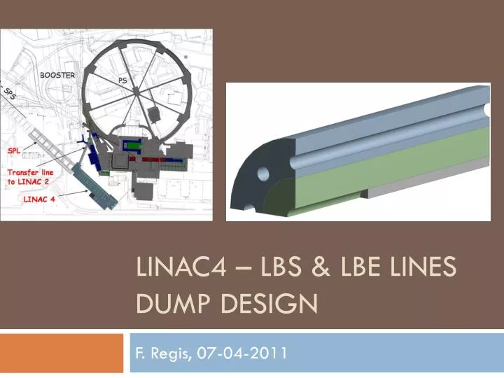
LINAC4 – LBS & LBE Lines dump design F. Regis, 07-04-2011
Outline • LBS and LBE lines • Design specifications • Dump features • LBS dump: RP preliminary analysis • General design features • Energy deposition • Thermal analysis • Structural analysis • Conclusions and next steps • LBS dump: Scenario 1 vs. Scenario 2
LBS & LBE lines LBS line: Present layout LBS line LBE line
Design specifications LINAC4 Project Document No. L4-B-ES-0001 rev.1.0 LINAC4 standard pulses Most severe thermo-structural scenario for LBS dump: Accident Most severe thermo-structural scenario for LBE dump: Commissioning For fatigue stress evaluation: most severe duty cycle. Absorbing core diameter: LBE beam size at vertical measurement, re-scaled at 5-σ LBS line operational scenario LBE line operational scenario LBS line 1-σ beam size LBE line 1-σ beam size
Dumps features LBS Dump • Installation in the tunnel ceiling (≈4.5 m height) • dmin=200 mm from SEM grid (SEM grid vacuum tank, line installations, extra-shielding,...) • Reduced particle fluence beyond the dump (soil activation issues and possible effects on TP9 Gallery) • Reduced particle backscattering to the SEM grid • Feasibility study presented in March 2010 (R. Chamizo, V. Boccone): starting point LBE Dump LINAC4 full intensity beam (40 mA average current, 2834 W average power) Most stringent thermo-structural constraints w.r.t. LBS dump Reduced particle backscattering towards instrumentation Let’s try a common design
LBS dump: RP preliminary analysis Irradiation profile Fluka model • 2 months – 12 h/day @142 W • 1 month off • 2 years – 8h x 2/week @14 W Induced activity in the water circuit • More calculations needed to evaluate concrete thickness necessary to reach 2.5 µSv/h • SEM grid position still to be defined • Estimated activity based on steady water volume: conservative approach • Refined analysis ongoing Courtesy of J. Vollaire
General Design Features Cu10100 OFE Copper Jacket R4550 Graphite Absorbing Core Beam parameters • LBE: commissioning scenario • 400 µs • Rep. Rate = 1.11 Hz • Iavg = 40 mA • Pavg = 2834 W • Beam size: vertical measurement scenario
Energy deposition Fluka • Peak energy deposition: 0.833e9 J/m3 • Nominal deposited power: 2834 W • Total deposited power ≈ 2419 W • Peak coordinates: zpeak = 265 mm ANSYS • Peak energy deposition: 0.804e9 J/m3 (-3.5% w.r.tFluka) • Total deposited power ≈ 2554 W (+5.6% w.r.t. Fluka)
Thermal analysis Steady state – 4 c.p. Vs. 8 c.p. ncp= no. of cooling pipes • Maximum water speed to prevent from erosion/corrosion problem = 1.5 m/s • Nominal Heat convection coefficient in cooling pipes = 7157 W/m2/K • Perfect thermal contact Graphite/Copper • ΔTin&out = 0.44 K (1/4th model) • Δpss ≈ 0.012 bar (1/4th model – straight section only)
Thermal analysis Transient analysis – Heat convection efficiency
Thermal analysis Absorbing Core – Regime Tmax Jacket – Regime Tmax Tmax=450°C Tmax=29°C Nominal convection Cooling pipe – Regime Tmax,wall Tmax=27°C
Structural analysis • Quasi-Static Structural analysis (worst cooling scenario): • First pulse: analysis of stress field in Graphite • ith pulse on regime: global analysis of stress field • Failure criteria: • Stassi Criterion for Graphite • VonMises Criterion for cooling jacket • Dynamic stress - Graphite • Heating process slower than stress relaxation due to elastic wave propagation
Structural analysis 1st pulse – Stassi criterion Tension 1st pulse – Stassi criterion Compression σmax=3.30MPa σmax=-28.72MPa Beam 500st pulse – Stassi criterion Tension 500st pulse – Stassi criterion Compression σmax=3.88MPa σmax=-31.3MPa
Structural analysis End 1st pulse – Von Mises σmax=0MPa • Stress levels within failure limits for both Graphite and Copper • No relevant mechanical properties degradation of Cu10100 (Tmax = 36°C) 500st pulse – Von Mises Next steps σmax=13.5MPa Thermal conductance model between graphite core and copper jacket Definition of the assembly interference (shrink fitting) Fatigue analysis for the dump – worst case scenario
Conclusions and Next Steps A common solution for the LBS and LBE dump seems possible: further analysis needed Worst case for thermo-structural analysis have been selected for the LBE dump Dump configuration has been set according to LBS operation specification (back-scattering) Thermal analysis for cooling system design: steady-state and transient state Structural analysis performed on worst cooling conditions WHAT IS NEXT? Thermal conductance model for graphite to copper interface Refined thermo-structural analysis: assembly interference, ... Detailed analysis of cooling water activation (RP) Possible reduction in dump size: open discussion with RP team
LBS Dump: Scenario 1 vs. Scenario 2 L s1 d l2 s2 d/2 lSEM l1 s3 H zMagnet zWall h
LBS Dump: Scenario 1 vs.Scenario 2 • Scenario 1: bending magnet (α=54°) and slit. The LBS dump placed in the tunnel ceiling. • Scenario 2: bending magnet (α=35°) and no slit. The LBS dump placed in the tunnel shielding. • First guess dimensions: 1.5 m max. length, 50 cm max diameter. • Preliminary discussion with Civil Engineering (N. Lopez-Hernandez): • Scenario 1: more complicated installation. Detailed analysis of dump infrastructure needed. • Scenario 2: slot for dump will be drilled. No need for wall partial dismantling. • Time of operation: ≈3-5 days. • Drilling machine encumbrance: ≈1 m machine width + 1 m on each side. • Preliminary discussion with RP (J. Vollaire): • Scenario 1: detailed evaluation of soil activation (fluence to TP9 gallery to be checked) • Scenario 2: issues about particle fluence to PSB tunnel