Download
1 / 9
90 likes | 271 Views
Status of studies for the transfer line between Linac4 and the PS booster (South Hall project). Purpose: Transport the beam from Linac4 to the booster and meet PSB injection requirements so that beam can be captured in the ring with small losses.

E N D
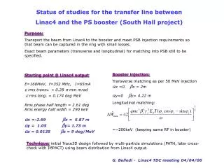
Status of studies for the transfer line between Linac4 and the PS booster(South Hall project) Purpose: Transport the beam from Linac4 to the booster and meet PSB injection requirements so that beam can be captured in the ring with small losses. Exact beam parameters (transverse and longitudinal) for matching into PSB still to be specified. • Starting point @ Linac4 output: • E=160MeV, f=352 MHz, I=65mA • e rmstransv. = 0.28 p mm mrad e rms long. = 0.174 deg MeV • Rms phase half length = 2.61 degRms energy half width = 290keV • ax =-2.69 bx = 5.87 m ay = 1.05 by= 1.73 m az = 0.0135 bz = 9 deg/MeV Booster injection: Transverse matching as per 50 MeV injection ax =0. bx = 2m ay=0 by= 4.22 m Longitudinal matching: =~200keV (keeping same RF in booster) Technique: initial Trace3D design followed by multi-particle simulations (PATH, later cross-check with IMPACT) using beam distribution from Linac4 output. G. Bellodi - Linac4 TDC meeting 04/04/06
Design approach: • Three main building blocks: • FODO channel for transport in the straight segments, to provide regular transverse focusing of the beam: • Q l= 600 mm • Qf = 1.5 T/m • L=7.2 m • s0 ~ 90o • mm bore diameter QF QD QF QD ~7.2 m
Energy spread increase due to space charge saturates after ~18 m Need to reduce energy spread of the bunch to <200 keV with one or more debuncher cavities. D Phi < 50deg to avoid RF nonlinearities
2) Buncher cavities : First one to be positioned at a distance of 20-30 m from Linac4 output (see plot) Voltage required: V~ DW/cos(Df)~= 900 keV/cos(40o)=1.2 MV Solution suggested by M.Vretenar is to use 4-cell cavities: Max 0.3 MV per cell 1.2 MV total Power limit 80kW 1m One cavity (@ full voltage) would probably just be sufficient for debunching, but second one (though at much lower voltage) would help to keep a larger margin to play with in meeting injection requirements on energy spread. Studied at 65mA, in first approximation no strong sensitivity on beam current. Keep bore diameter <40 mm Focus beam in the cavity
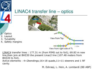
3) Bends • Straight layout not feasible (not a green-field construction) -> need to add bendings. • Two problems introduced: • Dispersion : • Achromatic solution of splitting the dipoles into two magnets and embedding them into a FODO period, then using 2 internal quads to match for Dx=0 D’x=0. • 2) H- ion stripping: • particle moving through magnetic field B will experience an electric field that can cause stripping • % stripped = 100% [ 1-exp(-t/t)] t(B)=7.96E-6/(cbgB)*exp(4.26E9/(cbgB)) • Calculated for q=60o, r~2m, B(T)=1T -- losses<0.01% • Aim to stay below magnetic fields of ~1T in dipoles. Q q/2 Q Q Q q/2 L = 7.2m Match for
Latest scheme achromats LINAC2
Summary • From a preliminary study of the transport line we’d need: • ~32 quadrupoles • 2 rf cavities (@ 1.2MV and ~0.4 MV approx.) • 3bendings (45o, 22o, 65o split in two halves of q/2) • FODO system for transporting and matching the beam can be done with standard quadrupoles for a wide range of currents. Next step is to couple quadrupoles on same power supply (cost driver for the line). • Couple pair of dipoles on a single power supply. • Total length is ~110m (of which ~32.5m – minus elements’ lengths - in PS tunnel would need Mu-metal magnetic shielding). • Civil engineering: build 2 tunnels (wide enough to fit quadrupoles inside) through PS/Linac4 shielding and PS/LEIR injection line, perhaps widen passage at the end of Linac3 building (not too painful!) • RP: initial study (location independent) based on 1 W/m level losses – unif. distributed- estimated at 230cm the minimum shielding thickness required for a Simple Controlled area. Revise for current layout and location (close proximity with Linac3/LEIR strengthen existing protection?)
Next steps: • Refine layout, try longer FODO periods to economise on number of elements. • More extensive and accurate beam dynamics studies with multiparticle simulations (using output beam distribution from Linac4) • Finalise exact layout, introduce steerers and diagnostics • Liaise with civil engineering to have an exact fit of the proposed layout in the context of existing structures and lines. • Radioprotection issues? • Final costing and TDR