EELE 414 – Introduction to VLSI Design
880 likes | 1.18k Views
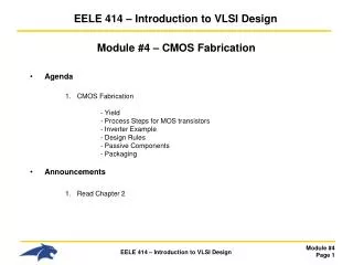
EELE 414 – Introduction to VLSI Design. Module #4 – CMOS Fabrication Agenda CMOS Fabrication - Yield - Process Steps for MOS transistors - Inverter Example - Design Rules - Passive Components - Packaging Announcements Read Chapter 2. CMOS Fabrication.

EELE 414 – Introduction to VLSI Design
E N D
Presentation Transcript
EELE 414 – Introduction to VLSI Design Module #4 – CMOS Fabrication • Agenda • CMOS Fabrication - Yield - Process Steps for MOS transistors - Inverter Example - Design Rules - Passive Components - Packaging • Announcements • Read Chapter 2
CMOS Fabrication • CMOS Fabrication- We have talked about 1) Device Physics of how materials act in a MOS/MOSFET structure 2) IV characteristics of the MOSFET device 3) Small geometry effects on transistor performance 4) Capacitances present in the MOSFET device 5) How we can use SPICE to simulate the behavior- we have seen that the properties of the materials play a major role in how the MOSFET performs- the properties of the material (which material, doping, sizes,..) come from the Fabrication of the MOSFET.- we want to understand how the devices are created so when we are designing, we can make educated decisions on what can and can’t be done to alter performance.
CMOS Fabrication • The Basics- We create the majority of our IC’s on Silicon- we take a Silicon Wafer, which is a thin disk of intrinsic Silicon- on this disk, we create multiple IC’s, which are square or rectangular in shape
CMOS Fabrication • The Basics- Once the wafer is processed, each individual IC is tested and marked whether it passed or failed- The individual IC’s are then cut out using a precision diamond saw.- the individual IC is called a “die”- the plural of this is “dies” or “dice”
CMOS Fabrication • The Basics- we define the : Yield = (# of Good die) (# of die on the wafer)- Yield heavily drives the cost of the chip so we obviously want a high yield. However, yields can be very low initially (i.e., <10%).- a mature process tries to hit ~90% yield
CMOS Fabrication • The Basics- since all of the IC’s on a wafer are processed together, the time it takes and the process steps required for the wafer are the same regardless of the # of IC’s on it.- this means the cost to process a wafer is the same whether it has 1 IC, or 1000 IC’s on it.- we can drive the cost down by: 1) Increasing the number of die on a wafer - smaller features (i.e., new processes, 1um, 0.8um, 0.25um, 90nm, 45nm) - larger wafers (2”, 4”, 8”, 12”, 16”) 2) Increasing yield - design changes - fab changes
CMOS Fabrication • Silicon Wafer Creation- The Silicon valence of 4 means that it can form a crystalline structure- This crystalline structure can be “grown”- we start with a Seed, which is a small piece of pure, crystalline Silicon- we then melt raw, impure Silicon into a crucible (aka, Silica)- we dip the Seed into the molten Silicon and pull it out slowly while turning- as the molten Silicon cools, it forms covalent bonds with the Seed- these bonds track the crystal structure of the Seed, forming more Silicon crystal
CMOS Fabrication • Silicon Wafers- As the Silicon is pulled out, it forms a long cylinder- this cylinder is called an Ingot- the ingot is a long cylinder of pure, crystal, Silicon
CMOS Fabrication • Silicon Wafers- The ingots are then cut into thin disks called Wafers- the wafers are polished and marked for crystal orientation- Companies specialize in the creation of ingots and typically sell the wafers to Fab shops
CMOS Fabrication • Photolithography- this is the process of creating patterns on a smooth surface, in our case a Silicon wafer- this is accomplished by selectively exposing parts of the wafer while other parts are protected- the exposed sections are susceptible to doping, removal, or metallization - specific patterns can be created to form regions of conductors, insulators, or doping- putting these patterns onto a wafer is called Photolithography- to understand this process, we must first learn about some basic components that are used in the process. We’ll learn these first and then put it all together to show how Photolithography is used to create an IC.
CMOS Fabrication Photoresist- a material that is acid-resistant under normal conditions- to begin with, it is insoluble to acids- when exposed to UV light, the material becomes soluble to acids- we can put photoresist on a wafer and then selectively expose regions to UV- then we can soak the entire thing in acid and only the parts of the photoresist that were exposed to UV light will be removed- this allows us to form a protective barrier on certain parts of the wafer while exposing others parts
CMOS Fabrication Photoresist- there are two flavors of photoresistOriginal StateAfter UV Exposure “Positive Photoresist” Insoluble Soluble “Negative Photoresist” Soluble Insoluble - Positive Photoresist is the most popular due to its ability to achieve higher resolution features
CMOS Fabrication Masks- a mask in an opaque plate (i.e., not transparent) with holes/shapes that allow UV light to pass- this is kind of like an overhead transparency - the mask contains the pattern that we wish to form on the target wafer- we pass UV light through the Mask and create soluble patterns in the photoresist- each pattern we wish to create requires a unique mask- the physical glass plate that is used during fabrication is called a Reticle
CMOS Fabrication Oxide Growth- Silicon has an affinity to form an Oxide when exposed to Oxygen- This forms Silicon Dioxide (SiO2), or oxide for short- SiO2 is an insulator- so all we have to do in order to form an insulating layer on Silicon is expose it to Oxygen- Silicon is actually consumed during this process
CMOS Fabrication Oxide Growth- There are two ways to provide the Oxygen for SiO2 growth “Dry Oxidation” - we use O2 gas in a chamber with the Silicon - this can achieve thin layers of SiO2 for gates, <100nm - No byproduct “Wet Oxidation” - we use water (H20) liquid as the source - the Silicon is submerged in water - this process can achieve thick layers of SiO2 for masking, 1-2um - the byproduct of this process is Hydrogen, which must be disposed of
CMOS Fabrication Oxide Growth- If heat is added to the process, the rate of SiO2 growth is sped up considerably- this is called “Thermal Oxidation” - applies to both Wet and Dry processes- temperatures usually are in the range of 700 – 1300 C
CMOS Fabrication Etching- Etching is the process of removing material from the substrate- Etches can remove Si, SiO2, polysilicon, and metal depending on what we want to accomplish
CMOS Fabrication Etching- there are two common types of etch processes “ Wet Etch” - also called Chemical Etch - this uses Hydrofluoric Acid (HF acid) - the wafer is submerged in the acid - simple, but produces toxic waste
CMOS Fabrication “ Dry Etch” - also called Plasma Etch - also called Reactive-Ion Etch (RIE) - plasma is a charged gas which has excited ions (i.e., free electrons in the outer orbital)- plasma can be moved by applying an E-field - the wafer is put in a chamber with an Anode and Cathode Disk on top and bottom - a gas is put in the chamber and charged to ionize it - the Anode is energized with an AC signal (13.56MHz) - this makes the plasma move back and forth between the Anode and Cathode - as the Plasma makes contact with the wafer, it will chemically react with the outer layers of the wafer - the chemical reaction forms a new compound that is loose and may be removed - since the ions move up and down, we can make a very vertical etch pattern
CMOS Fabrication Etching- when talking about etching, we typically talk about the etch patterns that can be formed Isotropic - etches equally in all direction - wet etch is isotropic - this etch leads to “undercutting” Anisotropic - the etch rate is dependant on the direction of the etch - dry etch is anisotropic undercutting
CMOS Fabrication Deposition- the process of “adding” material to the wafer (as opposed to growing, which consumes part of the target)- this is how we put down the polysilicon layer for the gate contact (in addition to insulators and metal)- Polysilicon is a polycrystalline material (SiH4) which is a conductor- Polysilicon originally starts with a high resistivity, but when doped its resistively comes down- the most common type of deposition is Chemical Vapor Deposition (CVD) Chemical Vapor Deposition - the wafer is put into a chamber with a gas (i.e., Si and H2) - the gas then forms a chemical reaction with the Silicon dioxide (SiO2) and Silicon to form a bond, the polysilicon is then added via chemical reactions. - somewhat similar to dry oxidation, but without the consumption of the wafer - this process can be used for polysilicon, metals, SiO2 and Nitride (Si3N4)
CMOS Fabrication Ion Implantation- the process of adding impurities to a silicon wafer - the wafer is put in a chamber with an Ion source (i.e., B, P, As)- the Ions are accelerated toward the wafer using an E-field- the Ions collide with the wafer, tunneling into the crystal structure
CMOS Fabrication Ion Implantation- photolithography allows us to selectively implant the regions we want (i.e., N-wells, Sources, Drains)- as the impurities crash into the crystal, they damage or break the covalent bonds- we can repair these bonds using a process called annealing, which heats the material up and then slowly cools it down allowing the new bonds to form
CMOS Fabrication • Fab Processes- Now we have all of the basic ingredient for an IC Fab:Silicon Wafer Creation - Ingots are grown in crucible starting with a Seed crystal. The ingots are cut into thin disks and polished to form the Si wafer.Photolithography - Transferring a pattern to the wafer using masks to selectively expose regions to UV light with either protect or expose areas on the wafer.Photoresist - Normally insoluble material which becomes soluble when exposed to UV light. The soluble regions can be removed by acid to expose the regions beneath. Oxide Growth - Growing an SiO2 directly on the Silicon wafer using either a Wet or Dry process. The growth consumes part of the wafer.Etching - process of removing material (Si, SiO2, polysilicon, metal) using either a wet (chemical) or dry (plasma) process.Deposition - Process of adding material (SiO2, nitride, poly, metal) using CVD/PVDIon Implantation - Process of adding impurities or doping (ni NA, ND)
CMOS Fabrication • Bulk Doping- The first step in creating an IC is to dope the entire Si wafer to p-type- For a CMOS process, both NMOS and PMOS transistors are present- Remember that: N-Channel transistors require P-type substrates P-Channel transistors require N-type substrates - we can avoid the process of selectively doping each N-channel and P-channel’s substrate region by doping the entire wafer first- So should we dope the whole thing N-type or P-type? - there are going to be many more N-Channel devices on the wafer - SRAM requires 6 transistors (4 NMOS, 2 PMOS) - DRAM requires 1 transistors (1 NMOS) - other circuit techniques exists in addition to CMOS that only use NMOS transistors for higher performing logic circuitry.
CMOS Fabrication • Bulk Doping- with the entire wafer being p-type, we can directly form N-channel devices- to make a p-channel device, we create a region of n-type material to act as the local substrate- this is called an N-well.
CMOS Fabrication • Bulk Doping- sometimes we wish to dope the P-type substrate even further than what is provided by bulk doping- we can create a P-well region to increase the substrate doping density (NA)- this configuration is called a Twin Tub- we won’t use this in EE414, but we want to know what people mean when they say Twin Tub
CMOS Fabrication • Active Regions (Device isolation) - when we create multiple transistors on the same substrate, the electrical operation of one transistor can effect the operation of adjacent transistors - coupling - inadvertent inversion layers - parasitic conduction paths- the first step in fabrication is to create an isolation layer on the wafer that defines where the MOSFETs will be located. - this isolation region is made up of SiO2called Field Oxide and Channel-Stop Implants (p+)- this Oxide region is relatively thick and sometimes called Thick Oxide (thin oxide is what we call the gate oxide)- the regions of exposed Silicon where we will put our MOSFETs are called Active Regions Active Regions Device Isolation
CMOS Fabrication • Active Regions (Device isolation) - One of the most popular techniques to create isolation between Active Regions is calledLocal Oxidation of Silicon (LOCOS)- In LOCOS, we selectively grow field oxide (as opposed to growing it everywhere and then selectively etching)- this has the advantage of actually recessing into the Silicon, i.e., consuming some of the Silicon in order to form a more planar surface- the isolation regions are formed by two layers 1) p+ channel stop implants 2) thick SiO2 insulator (Thick Oxide or Field Oxide)
CMOS Fabrication • Active Regions (Device isolation) - The first step is to cover the Active Regions so that when we dope the channel-stop implants, the active regions are protected- We use Nitride (Si3N4) to protect these regions. It inhibits SiO2 growth- Nitride is a good material for shielding but has a very different coefficient of thermal expansion than Silicon. As such, it can put a lot of mechanical stress on the wafer when heated and lead to cracks.- To avoid this, we put a layer of thin oxide (SiO2) in between the Nitride and Silicon wafer which absorbs the mechanical stress.- this oxide is called stress-relief oxide
CMOS Fabrication • Active Regions (Device isolation) - Next, we implant Boron into the exposed Silicon to form the Channel-Stop Implants- Then we grow thick Oxide on the exposed regions, noting that Oxide will not grow on the Nitride- The Oxide will consume part of the Channel-Stop-Implants
CMOS Fabrication • Review- We've talked about the basic process steps that are required for IC fabrication - Crystal growth - photolithography, photoresist, masks - oxide growth - etching - deposition - ion implantation- We've started talking about the major process stages: - Bulk Doping - Isolation (Active Region, LOCOS) - Now let's put everything together and walk through the creation of a full CMOS inverter
CMOS Fabrication • Major Process Steps- this flow chart shows the major process steps for a CMOS integrated circuit fabrication
CMOS Fabrication • Major Process Steps- Let's look at the design of a CMOS inverter: - some things to note: - this takes both an NMOS and PMOS - we need body connections for each MOSFET - the Gates are connected together (poly) - the Drains are connected together (metal)
CMOS Fabrication • CMOS Inverter Fab- We start by creating the N-well (for the P-channel devices) and the Channel-stop implants- this takes two full process/photolithography steps- things to note: - the photoresist by itself will not shield the Silicon from Ion Implantation. As a result, we use Oxide or Nitride to block the implants. - we remove the hardened (insoluble) photoresist using a chemical such as Acetone - We can etch away Oxide or Nitride - We need the Oxide/Nitride to be thick enough to completely block the implants - The Ion implants actually go through the photoresist and hit the Oxide.
CMOS Fabrication • CMOS Inverter Fab- We now grow the Field Oxide on top of the Channel Stop Implants to complete the Isolation Regions. Note that: - the Nitride prevents Oxide growth over the Active Regions - once the Oxide has grown, we need to remove the Nitride/Oxide regions using another photolithography step - notice these regions are the negative of Mask #2 so it is possible to use Negative photoresist and Mask #2 to save a reticle. - Once this is done, we have defined the Active Regions, which are where the MOSFETs will be located.- We begin creating the MOSFETs by growing the Field Oxide (thick)
CMOS Fabrication • CMOS Inverter Fab- We now deposit the polysilicon layer using chemical vapor deposition - this will act as the Gate contact - sometimes metals are used such as Aluminum - we pattern the material using a Dry Etch to get an anisotropic pattern
CMOS Fabrication • CMOS Inverter Fab- We now implant or dope the Source, Drain, and Body contacts - remember that Polysilicon has a high resistivity at this point. It will need to be doped for it to become a low-resistive conductor.
CMOS Fabrication • CMOS Inverter Fab- A note on Substrate Connections: - the NMOS needs a Body contact the same as the Source (GND) - the PMOS needs a Body contact the same as the Drain (VDD) - a Metal to lightly doped semiconductor forms a poor connection called a "Shottky Diode" - when making a metal connection to a semiconductor, we need to form an "Ohmic contact", which has a linear IV curve (i.e., a resistor). - The Ohmic contact is formed by heavily doping the Semiconductor prior to attaching the metal - We use p+ doping for the NMOS Body contact - We use n+ doping in the N-well for the PMOS Body contact
CMOS Fabrication - this picture doesn't show the NMOS body contact
CMOS Fabrication • CMOS Inverter Fab- Now we are ready to add the Metal contacts for the Source/Drain/Body - the first thing we do is put an insulating layer of SiO2 over the entire wafer using CVD - note that this is deposition instead of growth because we don't have access to the Silicon wafer to start the SiO2 growth - we then use a photolithography step to expose the contact windows, which is where the metal interconnects will go - the metal contacts are made to the deposition regions (Source/Drain/Body) and to the Gate (Polysilicon) - Metal (aluminum) is then deposited over the entire wafer using metal evaporation (similar to CVD) - the Metal lines are then patterned through another photolithography step.
CMOS Fabrication • CMOS Inverter Fab- Things to note - This metal layer is called "Metal 1". - the metal layer goes on top of a very non-planar surface