Download
1 / 32
340 likes | 423 Views
Learn about op-amp basics, characteristics, modes, impedance, feedback effects, and compensation in this comprehensive guide.

E N D
Objectives • Describe basic op-amp characteristics • Discuss op-amp modes and parameters • Explain negative feedback • Analyze inverting, noninverting, voltage follower, and inverting amp configurtions • Describe the impedance characteristics of the three op-amp configurations • Discuss op-amp compesation • Troubleshoot op-amps
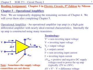
Introduction To Operational Amplifiers The operational amplifier or op-amp is a circuit of components integrated into one chip. We will study the op-amp as a singular device. A typical op-amp is powered by two dc voltages and has an inverting(-) and a noninverting input (+) and an output. Note that for simplicity the power terminals are not shown but understood to exist.
Introduction To Operational Amplifiers While an ideal op-amp has infinite gain and bandwidth, we know this is impossible. However, op-amps do have very high gain, very high input impedance, very low output impedance, and wide bandwidth.
Introduction To Operational Amplifiers It is interesting that the op-amp is internally made up of circuits that we have discussed in previous chapters.
Introduction To Operational Amplifiers In single ended input mode one input is grounded.
Introduction To Operational Amplifiers With the differential input mode two out-of-phase signals are applied with the difference of the two amplified and produced at the output.
Introduction To Operational Amplifiers With common mode input two signals of same phase, frequency, and amplitude are applied to the inputs which results in no output. This is called common-mode rejection. This type of mode is used for removal of unwanted noise signals.
Introduction To Operational Amplifiers The common-mode rejection ratio (CMRR) is the measure for how well it rejects an unwanted the signal. It is the ratio of open loop gain (Aol) to common-mode gain (Acm). The open loop gain is a data sheet value. CMRR = Aol /Acm
Introduction To Operational Amplifiers Op-amps tend to produce a small dc voltage called output error voltage (VOUT(error)). The data sheet provides the value of dc differential voltage needed to force the output to exactly zero volts. This is called the input offset voltage (VOS). This can change with temperature and the input offset drift is a parameter given on the data sheet.
Introduction To Operational Amplifiers There are other input parameters to be considered for op-amp operation. The input bias current is the dc current required to properly operate the first stage within the op-amp. The input impedance is another. Also, the input offset current which can become a problem if both dc input currents are not the same. Output impedance and slew rate, which is the response time of the output with a given pulse input are two other parameters. Op-amp low frequency response is all the way down to dc. The high frequency response is limited by the internal capacitances within the op-amp stages.
Negative Feedback Negative feedback is feeding part of the output back to the input to limit the overall gain. This is used to make the gain more realistic so that the op-amp is not driven into saturation. Remember regardless of gain there are limitations of the amount of voltage that an amplifier can produce.
Op-Amps With Negative Feedback The closed-loop voltage gain (Acl) is the voltage gain of an op-amp with external feedback. The gain can be controlled by external component values. Closed loop gain for a non-invertingamplifier can be determined by the formula below. A cl(NI) = 1 + Rf/R1
Op-Amps With Negative Feedback The voltage-followeramplifier configuration has all of the output signal fed back to the inverting input. The voltage gain is 1. This makes it useful as a buffer amp since it has a high input impedance and low output impedance.
Op-Amps With Negative Feedback The inverting amplifier has the output fed back to the inverting input for gain control. The gain for the inverting op-amp can be determined by the formula below. A cl(I) = Rf/R1
Effects Of Negative Feedback On Op-Amp Impedances However high the input impedance of an op-amp circuit is, impedance still exists. For a non-inverting amplifer it can be determined by the formulas below. B(feedback attenuation) = Ri/Ri + Rf Zin(NI) = (1 + AolB)Zin
Effects Of Negative Feedback On Op-Amp Impedances The output impedance is understood to be low for an op-amp. It’s exact value can be determined by the formula below. Z(out) = Zout/1 + AolB
Effects Of Negative Feedback On Op-Amp Impedances The input impedance for an inverting amplifier is approximately equal to the input resistor (Ri). The output impedance is very low and in most cases any impedance load can be connected to it with no problem. The exact amount can be determined by the formulas below. B(feedback attenuation) = Ri/Ri + Rf Zout(I) = Zout / (1 + AolB)
Bias Current And Offset Voltage Compensation Input bias current creates an output error voltage which must be compensated for in all of the op-amp configurations. For the voltage-follower this error voltage can be reduced with resistors of the same value in the feedback loop and input.
Bias Current And Offset Voltage Compensation For the inverting and noninverting configurations this can be accomplished by a resistor in the non-inverting part of the circuit that has the same value as the feedback resistor.
Bias Current And Offset Voltage Compensation Input offset voltage is small but unavoidable because of internal characteristic differences. The offset null terminals and a potentiometer connected as shown can eliminate this.
Open-Loop Response The open-loop gain of an op-amp is determined by the internal design and it very high. The high frequency cutoff frequency of an open-loop op-amp is about 10Hz.
Open-Loop Response The internal RC circuit of an op-amp limits the gain at frequencies higher than the cutoff frequency. The gain of an open-loop op-amp can be determined at any frequency by the formula below. Aol = Aol(mid)/1 + f 2/fc2 Op-amp with internal RC circuit shown externally.
Open-Loop Response Of course as with any RC circuit phase shift begins to occur at higher frequencies. Remember we are viewing internal characteristics as external components.
Closed-Loop Response Op-amps are normally used in a closed loop configuration with negative feedback. While the gain reduced the bandwidth is increased. The bandwidth (BW) of a closed-loop op-amp can be determined by the formula below. Remember B is the feedback attenuation. BWcl = BWol(1 + BAol(mid))
Closed-Loop Response The gain-bandwidth product is always equal to the frequency at which the op-amp’s open-loop gain is 0dB (unity-gain bandwidth).
Troubleshooting You can only troubleshoot an op-amp as a single device even though it can be quite complex internally. Let’s look at some common failures of the op-amp and the effects of associated external component failure.
Troubleshooting With an open feedback resistor (Rf) in a non-inverting amplifier the op-amp’s gain goes up to the open loop gain. The result would be severe clipping of the output signal.
Troubleshooting With an open input resistor (Ri) the gain would drop to approximately 1. Other signal degradation would be indicative of internal op-amp failure.
Troubleshooting An open feedback resistor in an inverting amplifier would have similar effects as a noninverting amplifier. An open input resistor would prevent the input signal from reaching the amp. Internal op-amp failures would be the main suspect with a voltage follower aside from external connection problems.
Summary • The basic op-amp has three terminals: inverting input (-), noninverting (+), and output • An op-amp has a very high open-loop gain, very high input impedance, very lower output impedance, and wide bandwidth. • Common-mode ocurs when equal in-phase voltages are applied to both terminals, which results in no output. • Input offset voltage and current produce an error voltage at the output. These can be compesated for by external components. • Gain can be controlled by a resistive feedback loop.
Summary • The three op-amp amplifier configurations are inverting, non-inverting, and voltage follower. • The bandwidth of an op-amp is equal to the upper critical frequency (fcu). • The bandwidth increases as the gain is decreased. • The internal RC circuits are responsible for high frequency roll off. • The gain-bandwidth product equals the frequency at which unity voltage gain occurs.