Download
1 / 17
170 likes | 189 Views
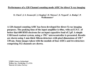
A 128-channel ASIC designed for direct X-ray imaging with a peak time of 60ns and E.N.C. of over 600 RMS electrons. The ASIC uses a USB-based readout system and is implemented in 0.25um CMOS technology. Results include testing with Silicon detectors and pixel dimensions, and images taken with multiple ASICs and detectors.

E N D
Performance of a 128 Channel counting mode ASIC for direct X-ray imaging E. Chesi1, J. S. Iwanczyk2, J. Kaplon1, D. Moraes1, E. Nygard3, A. Rudge1, P. Weilhammer1 A 128 channel counting ASIC has been developed for direct X-ray imaging purposes. The peaking time of the input amplifier is 60ns, with an E.N.C. of better that 600 RMS electrons for an input capacitive load of 2 pF. A simple USB based readout system, using a ‘PIC’ microcontroller is presented. Results are shown using 1 mm thick Silicon detectors with pixel dimensions of 130 * 130 um. Some images taken with the module of four ASICs and two detectors comprising 512 channels are shown. 1CERN, Geneva, Switzerland 2DxRay, Inc., Northridge, CA, USA 3Interon AS, Asker, Norway
Fig.1 Block diagram of the ASIC architecture The ASIC is implemented in 0.25um CMOS technology. The transimpedance pre-amplifier [1] and Shaper form a CR-RC filter with a peaking time of 60ns. 2 test inputs to individual channels are provided via a 0.1pF capacitor. The two discriminators have externally determined thresholds enabling simple energy discrimination. Fine adjustment of individual thresholds is possible using 5 bit internal trimdacs which are preloaded from a serial shift register. The discriminators are followed by a 25ns monostable. The counters are multiplexed together and read out as 18 parallel bits at speeds greater than 20 Mhz. [2]
A PIC [3] microcontroller was chosen to maximize simplicity and flexibility. It is programmed in assembly language in situ. via a second USB interface. The instruction cycle is executed at 10 Mhz. The PIC provides all the control signals for the ASIC, also timing information for the 18 bit FIFO and ‘hand shakes’ for the USB interface. The trimdac serial data from the P.C. is reformatted by the PIC and passed to the ASIC at the start of each run. An ASCII display is included for debugging purposes. Fig.3
Performance of the 17ch. Prototype [2] Fig.4 Detector 1mm Si. 250V Am 241 Pulse Generator 2mV into 1.8pF. at the input. Threshold scanwith Am.241 Source Histogram of pulse heights Am 241 Linear Channel
Pulse generator threshold scan of a single channel of the 128 channel ASIC, with an input of 5 *10 fC. The bias values are set to accept positive inputs. The 128 channel ASIC has no analog channel, the bias settings were optimized using the 17 channel prototype. Pulse generator scan of all channels with threshold setting of 180. Fig. 5
Fig. 7 The signal amplitude as determined from a threshold scan with pulse generator input. Good agreement with the source data is observed. A threshold lower than 20 Kev. seems to be possible.
Fig. 8 The complete module with four ASICs and two detectors, 512 pixels
Fig. 9 90 The detector assembly shown in the previous slide was tested with a Sr. source at a fixed threshold. All 512 channels were observed to count, and the geometrical effect of the source close to the detector can be clearly seen.
Fig. 10 A three dimensional “lego” plot of channel No. (long axis) versus threshold. The ASIC has a known and understood systematic gain variation, however other effects are seen, which, when understood may be removed with the trimdac adjustment.
Fig. 11 First attempts at imaging. Pixel size is 130um *130 um. A 3mm section square steel bar was placed above the detector and the assembly was illuminated with two different sources. The image can be clearly seen. Some dead channels are observed.
Fig. 12 A 1 mm hole was then drilled in the previously mentioned bar and imaged With a Am source. The hole can be clearly observed. 241 The hole was then repositioned by half its diameter and again imaged, producing the plot shown below.
Fig. 13 Stepping motor driven linear actuator producing 130um steps
Fig. 14 Initial results from imaging the metal bar using the moving assembly
References [1] P.Jarron et al. A Transimpedance amplifier using a novel current mode feedback loop. N.I.M. A, vol 377, pp435-349, 1996 [2] D. Moraes et al. Front-End Counting Mode Electronics for CdZnTe Sensor Readout. IEEE Nuclear Science Symposium 2004 [3] Microchip Technology Inc. Chandler, AZ 85224-6199 USA Acknowledgements The authors would like to thank Richard Grey from the University of Auckland for the preparations of the lego plots.
Conclusions The performance of a 128 Channel counting mode ASIC developed for direct X-ray imaging, together with the sensor, consisting of 256, 130um * 130um pixels specially developed for this application, has been tested as a complete system. The silicon pad sensor is 1 mm thick and was designed to be ‘edgeless’ (130um from the last pixel to the cutting edge) allowing several detectors to be positioned next to each other to minimize dead space. The readout system used has been described. A simple linear scanning device has been shown to be operational, and preliminary images presented. The functionality of the ASIC has been proven, and known problems are under investigation. The use of the trimdac has not yet been implemented, but it is expected that it will perform its design function and significantly reduce channel to channel variations. A four ASIC and detector assembly has been constructed, and presented here. Future development will concentrate on further system improvement.