Download
1 / 31
310 likes | 536 Views
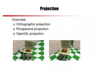
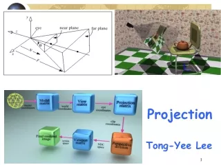
Projection. Projection - the transformation of points from a coordinate system in n dimensions to a coordinate system in m dimensions where m<n.

E N D
Projection • Projection - the transformation of points from a coordinate system in n dimensions to a coordinate system in m dimensions where m<n. • We will be talking about projections from 3D to 2D, where the 3D space represents a world coordinate system and the 2D space is a window which is mapped to a screen viewport.
Specifying a Projection • Two things must be specified • Projection plane and a center of projection. • Projection plane • A 2D coordinate system onto which the 3D image is to be projected. We’ll call this the VRP for view reference plane. • Center of projection • A point in space which serves as an end point for projectors. We’ll refer to this point as the COP. It is also called a PRP for a projection reference point.
Projectors • Projectors - a ray originating at the center of projection and passing through a point to be projected. Here is an example of a projection:
Parallel Projection • A simple case of a projection is if the projectors are all in parallel. • What does this imply about the COP?
Direction of Projection • We can’t specify the COP for parallel projection • We’ll use Direction of Project (DOP) instead
Some Trivia • Planar geometric projection • A projection onto a planar surface (planar) using straight lines (geometric). • Foreshortening • Varying lengths of lines due to angle of presentation and/or distance from center of projection. Applies to both parallel and perspective projections.
Orthographic Projections • Orthographic projection • parallel projection with the direction of projection and the projection plane normal parallel. • Elevation • an orthographic projection in which the view plane normal is parallel to an axis. • The three elevations • front-elevation • top-elevation (plan-elevation) • side-elevation.
Axonometric orthographic projections • Axonometric orthographic projections • Use projection planes which are not normal to an axis. They show more than one face of an object at a time. They induce uniform foreshortening unrelated to depth. • AOP preserves parallelism of lines. It does not preserve angles.
Isometric projection • Isometric projection • Axonometric orthographic projection where the projection plane normal (and the direction of projection) makes identical angles with each principle axis. How many of these are there?
Oblique Projection • Oblique projection • the projection plane normal and the direction of projection are at angles to each other. DOP VPN
Cavalier Projection Why? • An Oblique projection • DOP is at 45 degree angle to VPN • Lines parallel to any axis are foreshortened equally. Lines parallel to the z axis appear at an angle a, which is dependent upon the direction of projection. • Two common projections have a as 45° and 30°. 45o 30o
Cavalier Projection Angles DOP VPN
Cabinet projection • Oblique projection • projection plane normal is at an arctan(2) = 63.4° degree angle to the projection plane. (typically projecting onto the x,y plane) • Lines parallel to the axis defining the projection plane are foreshortened equally. Lines parallel to the projection plane normal are halved!
Cabinet Projection DOP 63.4o VPN
y z Parallel Projection • After transforming the object to the eye space, parallel projection is relative easy – we could just drop the Z Xp = x Yp = y Zp = -d • We actually want to keep Z – why? (Xp, Yp) (x,y,z) x
Parallel Projection (2) • OpenGL maps (projects) everything in the visible volume into a canonical view volume (xmax, ymax, -far) (1, 1, -1) (xmin, ymin, -near) (-1, -1, 1) glOrtho(xmin, xmax, ymin, ymax, near, far) Canonical View Volume
Parallel Projection (3) • Transformation sequence: 1. Translation (M1): (-near = zmax, -far = zmin) -(xmax+xmin)/2, -(ymax+ymin)/2, -(zmax+zmin)/2 2. Scaling (M2): 2/(xmax-xmin), 2/(ymax-ymin), 2/(zmax-zmin) 2/(xmax-xmin) 0 0 - (xmax+xmin)/(xmax-xmin) M2 x M1 = 0 2/(ymax-ymin) 0 - (ymax+ymin)/(ymax-ymin) 0 0 2/(zmax-zmin) -(zmax+zmin)/(zmax-zmin) 0 0 0 1
Perspective Projection • Perspective projections have projectors at angles to each other radiating from a center of projection. • Parallel lines not parallel to the projection plane will not appear parallel in the projection.
Vanishing Points • If not parallel? • If the lines are not parallel anymore, they must meet somewhere. In 3D space that point will be at infinity and is referred to as a vanishing point. There are an infinite number of vanishing points. • Axis vanishing points • Lines parallel to one of the major axis come to a vanishing point, these are called axis vanishing points. Only three axis vanishing points in 3D space.
Center of Projection in OpenGL • OpenGL always puts the center of projection at 0,0,0 • The projection plane is at z = -d • This is sometimes called the “focal length” or “f”
glFrustum(left,right,bottom,top,znear,zfar) Frustums • The region we can see is called the frustum (right,top,-znear) (0,0,0) -zfar (left,bottom,-znear) znear and zfar are positive
gluPerspective • How do we get from: • gluPerspective(fovy, aspect, znear, zfar) • To • glFrustum(left,right,bottom,top,znear,zfar)
fov to near frustum (x,y,-znear) -z
Projection Structure Pinhole Camera Model of Projection y P(x,y,z) x Proportional! P'(x',y',z') -d -z
Matrix for Perspective Projection? • We need division to do projection! • But, matrix multiplication only does multiplication and addition • What about:
Homogenous Coordinates (again) • A 3D homogeneous coordinate: • (x, y, z, w) • We had been saying that w is 1 • But – • (x, y, z, w) corresponds to (x/w, y/w, z/w) • Dividing by w is called homogenizing • If w=1, x,y,z are unchanged. • But, if w=-z/d? • (x/(-z/d), y/(-z/d), z/(-z/d)) = (-dx/z, -dy/z, -d)
The Entire Viewing Process • Rotate world so that the COP is at 0,0,0 and DOP is parallel to the Z axis • Apply perspective projection • Homogenize • Viewport transformation
Viewport Transformation(Window to Viewport) • Window • Area of the projection plane • Typically some normalized area with 0,0 in the center • Viewport • Area of the computer display window • Example: • (0, 0) to (640, 480)
Window to Viewport Example • Assume Window (-1,-1) to (1,1) • OpenGL calls these normalized device coordinates • Viewport (0, 0) to (640, 480) • OpenGL calls these window coordinates
Perspective Projection (6) • Final Projection Matrix: x’ 2N/(xmax-xmin) 0 (xmax+xmin)/(xmax-xmin) 0 x y’ = 0 2N/(ymax-ymin) (ymax+ymin)/(ymax-ymin) 0 y z’ 0 0 -(F + N)/(F-N) -2F*N/(F-N) z w’ 0 0 -1 0 1 glFrustum(xmin, xmax, ymin, ymax, N, F) N = near plane, F = far plane
ObjectCoordinates ModelviewMatrix Eye coordinates ProjectionMatrix Clip coordinates Homogenize Normalized device coordinates (2D) Window toViewport Viewportcoordinates Within OpenGL glBegin(GL_POLYGON); glVertex3dv(a); glVertex3dv(b); glVertex3dv( c);glEnd();