Engineering Graphics: Projection Principles and Methods
Learn about projection in engineering graphics, including orthographic projection principles, methods of obtaining views, planes of projection, and projection quadrant patterns.

Engineering Graphics: Projection Principles and Methods
E N D
Presentation Transcript
MD.NASER AHMED asst profMECHANICAL ENGINEERING Sub- ENGINEERING GRAPHICS TOPIC-POINTS I YEAR I SEM
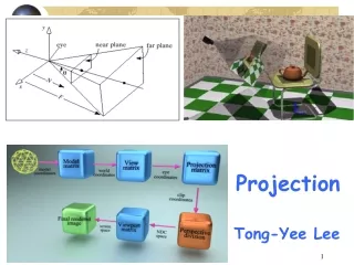
PROJECTION Any object has three dimensions, ie its length, width and thickness. A projection is defined as the representation of an object on a two dimension plane Principal of projection: If straight lines are drawn from various points on the contour of an object to meet a plane, the object is said to be projected on that plane. The figure formed by joining in correct sequence, the points at which these lines meet the plane, is called the projection of the object. The lines or the rays drawn from the object to the plane are called projectors
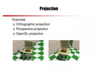
Methods of projection 1.Orthographic projection – ( 2D – view) 2.Isometric ( 3D or pictorial view) 3.Oblique ( 3D or pictorial view) 4.Prospective ( 3D or pictorial view)
Orthographic projection: When the projectors are parallel to each other and also perpendicular to the plane the projection is called orthographic projection. This projection views represents two dimensions of an object. For the complete description of the 3D object, more than one view is required
Method of obtaining orthographic projection Front View: the front view is obtained by looking the object normal to its front surface and projecting it on the vertical plane(V.P)Top View: the top view is obtained by looking the object normal to its top surface and projecting it on the horizontal surface.Side View: the side view is obtained by looking the object normal to its side surface and projecting it on the profile plane.
Planes of Projection: The planes used for the purpose of projection is called as the planes of projection or reference plane (or) Principal planes of projection. 1.Horizontal plane(H.P) 2.Vertical Plane(V.P) Reference line: The line of intersection of H.P and V.P is called as reference line(X-Y)
THIS QUADRANT PATTERN, IF OBSERVED ALONG X-Y LINE ( IN RED ARROW DIRECTION) WILL EXACTLY APPEAR AS SHOWN ON RIGHT SIDE. Projection planes and Four Quadrants HP VP 1ST Quad. 2nd Quad. Y HP X Y X 4th Quad. 3rd Quad. VP
Four quadrants When the planes of projection are extended beyond the line of intersection, they form four quadrants (or) dihedral angles which may be numbered I, II, III, IVThe object may be situated in any one of the quadrant its position relating to there plane is described as above H.P and in front of V.P . Above H.P and behind V.P First angle projection It is assumed that the object is placed in Ist Quadrant Third angle projection The object is assumed to be situated in the third quadrant
Difference between first angle projection and third angle projection
Rotation of planes: Once the object is assumed to be in one of the quadrant, H.P is rotated at an angle of 900 in clock wise direction, such that the H.P and V.P lies in the same plane.
NOTATIONS FOLLOWING NOTATIONS SHOULD BE FOLLOWED WHILE NAMEING DIFFERENT VIEWS IN ORTHOGRAPHIC PROJECTIONS. OBJECT POINT A LINE AB IT’S TOP VIEW a a b IT’S FRONT VIEW a’ a’ b’ IT’S SIDE VIEW a” a” b”
HP OBSERVER OBSERVER OBSERVER OBSERVER VP HP VP HP HP VP VP POINT A IN 1ST QUADRANT POINT A IN 2ND QUADRANT a’ A A a’ a a a a a’ A a’ A POINT A IN 4TH QUADRANT POINT A IN 3RD QUADRANT
For Tv POINT A ABOVE HP & INFRONT OF VP a’ For Fv VP X Y a HP PROJECTIONS OF A POINT IN FIRST QUADRANT. a’ A Y X a Fv above xy, Tv below xy.
For Fv For Tv ORTHOGRAPHIC PRESENTATIONS OF ALL ABOVE CASES. VP Y a’ X X Y a HP POINT A ABOVE HP & IN VP PICTORIAL PRESENTATION A a’ a Fv above xy, Tv on xy.
For Tv POINT A IN HP & INFRONT OF VP For Fv VP Y X a’ X Y a HP a’ a A Fv on xy, Tv below xy.
Q1) Draw the projection of the following points on the same ground line, keeping the projectors 25mm apart. 1. A point in HP and 20mm behind VP. 2. 40mm above HP and 25mm in front of VP. 3. In the VP and 40mm above HP. 4. 25mm below HP and 25mm behind the VP. 5. 15mm above HP and 50mm behind VP. 6. 40mm below HP and 25mm in front of VP. In both HP and VP.
b’ c’ d 40mm 40mm a 25mm 20mm a’ x c y 25mm 25mm d’ b
e 50mm e’ 15mm g’ x y g 25mm f 40mm f’
Q2) A point is 50mm from both the reference planes, draw its projections in all possible directions.
a a a’ a’ 50mm 50mm 50mm X Y 50mm 50mm 50mm a a a’ a’ Q1 Q2 Q4
Q3) Projections of various points are given below. State the positions of each point with respect to planes of projections. Mention distances in centimeters.
d e’ 3 c 3 e a’ 2 1.5 20 a b d’ X Y 4 3 c’ b’
1. A point in a V.P and 2cm above H.P2. A point in a H.P and 4cm in front of V.P3. A point 3cm below H.P and 2cm behind V.P4. A point in a H.P and 3cm behind V.P5. A point 1.5cm above H.P and 3cm behind V.P
Q4) A point P is 15mm above HP and 20mm in front of VP. Another point Q is 25mm behind the VP and 40mm below HP. Draw the projections of P and Q keeping the distances between projections equal to 90mm. Also draw straight lines joining their top views and front views.
Q P’ 25mm 15mm 90mm X Y 20mm P 40mm Q’
Q5) Two points A and B are in HP .The point A is 30mm in front of VP while the point B is behind VP .The distance between their projectors is 75mm and the line joining their top views makes an angle of 45˚with XY. Find the distance of point B from VP.
b ?mm 75mm X Y a’ b’ 30mm 450 a