Projection Displays
Projection Displays. OPT 696D. Contents. Requirements Inputs and Outputs Sub-Systems Conservation of é tendue Approaches and tradeoffs. Requirements. Cost Size and weight Noise Good looking image ANSI lumens Contrast Resolution Color gamut Subjective appearance

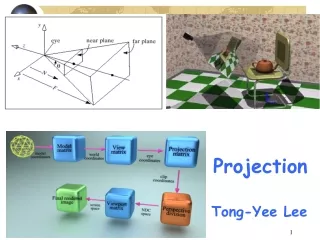
Projection Displays
E N D
Presentation Transcript
Projection Displays OPT 696D
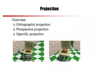
Contents • Requirements • Inputs and Outputs • Sub-Systems • Conservation of étendue • Approaches and tradeoffs
Requirements • Cost • Size and weight • Noise • Good looking image • ANSI lumens • Contrast • Resolution • Color gamut • Subjective appearance • Size and location of image
Inputs Power Video signal Focus/zoom inputs Image quality controls Outputs An image Audible noise Inputs and Outputs
Sub-Systems • Electrical • Thermal • Mechanical • Safety • Optical
Electrical Sub-System • Most inputs are electronic • This sub-system overlaps with the optical at the light valve • Includes the menu system for settings • Often includes buttons on housing as well as a remote control • Controls thermal sub-system
Thermal Sub-System • The light source generates significant heat • The source’s temperature can significantly impact its life and performance • Some types of light valves are more sensitive than others to temperature • Some liquid crystals turn into just liquids around 80oC
Mechanical Sub-System • This is what holds everything in place • One of the few areas where there is some control of cost • How loose are the assembly tolerances? • What compensators are appropriate?
Safety • Lamp needs high voltage to start • Lamp gets hot enough to cause burns • One failure mode of the lamp is explosive • Many lamps emit a significant amount of UV
Optical • Light source • Illumination system • Spatial/angular control • Color separation • Polarization • Light valve • Color combination (in some cases) • Projection lens • Screen (in some cases)
Conservation of Étendue • Start with a differential area and differential solid angle (i.e. differential étendue A1 1) • There will be some flux in this étendue • Propagate the light through an optical system and the flux will be contained in a new differential étendue A1 1= A2 2
Conservation of Étendue, Cont. • The assumptions are that a deterministic ray trace can fully describe the system • No scatter, diffraction or beamsplitters • Essentially the same thing as the Lagrange invariant or conservation of radiance • Each wavelength and orthogonal polarization state can be thought of as a separate source
Throughput vs. Étendue • I define throughput as the A product for finite areas and angles • The throughput for a F/2 lens and ½ in CCD is 6.47 mm x 4.80 mm x sin2(14.5 deg) • It is conceivable to not conserve throughput in a deterministic system • Use throughput because it is simple to calculate
Why Is This Relevant • Some portion of the optical system will have the lowest étendue • This should be set by the active area of the light valve and the NA of the projection lens • You can only use the lumens from the source that are contained in the same amount of étendue • Anything outside this étendue can not be used
Light Source • You need a source that has lots of lumens in a small étendue • The most common choice is a short arc, mercury, high intensity discharge lamp • Typical arc gap is approximately 1.2 mm for ≈ 7,000 lm at 120 W • 250 W lamps put out up to 15,000 lm Image from http://www.lighting.philips.com
Spectral Distribution • Mercury lamps do not have uniform spectral distribution • They typically are red deficient Image from http://www.lamptech.co.uk
LEDs for Projection • Luminus makes LEDs specifically for the projection display market • Phlatlight PT120 is largest LED set • 12 mm2 area for each die • Not quite Lambertian • Over 3,000 lm from set
Illumination System • A 4:3 aspect ratio rectangle has about 61% of the area of the circumscribed circle • A 16:9 aspect ratio rectangle has about 54% of the area of the circumscribed circle • Must form a uniform, rectangular “spot” • Spot must be aligned to the light valve • How much should the spot be oversized?
How To Get a Rectangular Spot • Light pipe • Source is imaged into input of rectangular lightpipe • If lightpipe is long enough, output is spatially uniform • Output surface is imaged onto light valve • Fly’s eye integrator
Lightpipe Approach • For modestly large angles, small changes in the input location result in large changes in the output location • For straight sides, the angular distribution does not change
How Do System Requirements Drive Lightpipe Design? • Size of reflector on lamp? • Size of input and output? • Length of lightpipe? • Size of light valve?
Fly’s Eye Description • Input into two lens arrays is narrow angle beam • There is one-to-one mapping from the first array to the second • All of the light from one element in the first array goes through its matching lens in the second array • The lens in the second array images the aperture of the first lens to infinity • A monolithic lens images all of the apertures onto the light valve
How Do System Requirements Drive Fly’s Eye Design? • Size of reflector on lamp? • Number of lens elements? • Spacing of arrays? • Size of light valve?
Light Valves • This is the device that spatially modulates the light to form the image • Three technologies are currently viable • High Temperature Poly-Silicon LCDs (HTPS or just LCD) • Digital Micro-mirror Device (DMD) • Liquid Crystal on Silicon (LCoS) • Single most expensive item on bill of materials
HTPS LCD • Transmissive device • Think of each pixel as an independently adjustable wave plate • Polarizer on each side of device • Illumination should not depart significantly from telecentric • Switching times support video rates • Up to 1.8” diagonals
DMD • Manufactured by Texas Instruments • A MEMS device where each pixel is a mirror that can tilt to an on or off state • In the on state, the mirror reflects light from the source into the entrance pupil of the projection lens • In the off state, the mirror reflects the light out of the pupil • Grey scale achieved with binary pulse width modulation • Up to 0.9” diagonals
Graphic of DMD concept TIR prism used to get light to and from DMD DMD, Cont. Image from http://www.oerlikon.com Image from http://focus.ti.com
LCoS • Reflective LCD • Can put processing on LCoS chip • Potential for high resolution • Late to the market so not as mature
Color Approaches • Three panel • Three separate light valves where the images are combined downstream • Field sequential • Each color image is shown sequentially • The colors are switched faster than the integration time of the eye
Three Panel • Key feature is X cube • A four piece prism with two different coatings Image from http://www.oerlikon.com
Field Sequential • Color wheel is most common • Rotating disk with different colors that is synchronized to video image • With LEDs, turn them on and off as needed Image from http://www.oerlikon.com
Polarization Conversion • LCDs can only use one polarization state • If the source étendue is smaller than the rest of the system, it is possible to gain from a polarization conversion system (PCS) • Adds cost and complexity, but gives you more lumens
How Does a PCS Work? PBS Fold mirror ½ plate
What About Étendue? • You can not superimpose two identical sources in both space and angle • The different polarization states are two separate sources • When you separate them and switch the polarization of one, you double the étendue of the source
Projection Lens • Typically fast • F/1.5 for LCD and F/2 for DMD • Large BFD through moderately high index glass • Some longitudinal chromatic aberration may be acceptable in a three panel system • Wide FOV • Wider for optical keystone correction • Zoom • Can’t depart from telecentric by too much
Screens • Screens are rated with a gain • Gain is the ratio of the on axis radiance generated by the screen compared to a Lambertain diffuser • Screen gain completely ignores angular distribution • Front projection screens are “easy” • Rear projection screens are “hard”
Front Projection • Relatively easy to get a white screen • Uniformity with angle is usually good • Typically viewed under well controlled lighting conditions • People are used to turning off the room lights • Resolution is typically not an issue
Rear Projection • Tradeoff between a “white” screen, uniformity, resolution and efficiency • Lighting environment is typically not as well controlled • Tinted substrate can provide contrast enhancement at the cost of lumens • Lenticular screens often used to direct light • High resolution applications can result in speckle