Download
1 / 70
720 likes | 867 Views
Explore the development and history of moving coil actuators in disk drives, from IBM's RAMAC to modern flat coil rotary actuators. Presented at SJSU IEEE Magnetics Monthly Meeting by Dr. J. Arthur Wagner. Learn about the basic purpose, design parameters, and crucial advancements in disk drive actuator technology.

E N D
History of Moving Coil Actuators in Disk Drives Presented at SJSU 5/19/18 IEEE Magnetics Monthly Meeting J. Arthur Wagner, Ph.D. Prof. Emeritus in Electrical Engineering SJSU
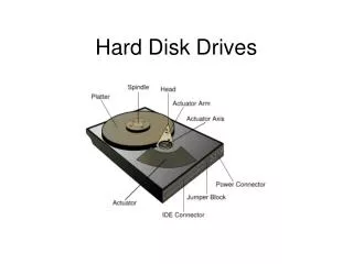
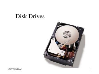
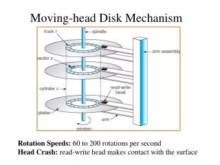
Basic Purpose of Disk drive Moving Coil Actuators • Disk drives store data magnetically. • The data is stored and located on concentric tracks on surfaces of disks. • Magnetic heads “fly” over the disk surfaces to write or read data to or from magnetic media on a disk. • The purpose of disk drive moving coil actuators is to position the magnetic heads over a track.
Contents • The basic magnetics of a moving coil actuators • Historical cases of actuators
IBM • Started operations in San Jose in c. 1956 • First location: downtown San Jose • First product: RAMAC c.1956 • IBM spawned other disk drive companies • In the 1970s IBM introduced the moving coil actuator using a 14” diameter disk.
Disks • 24” RAMAC 1956 50 disks 3.75 MB • 14” flying heads • 10” • 8” • 5 ¼” • 3 ½” • 2 ½” Today’s size • 1.8”
Voice Coil Motor: Like the short air gap, long coil, linear disk drive actuator Leads attached to a moving Coil mounted onto a cylinder. Air gap at inner edge of plate. Axially magnetized ferrite magnet. End plate
IBM Linear Actuator, Like a voice coil motor, “Long Coil”, probably weighed 25 lbs There was a shorted turn on this actuator, not shown. Explain purpose.
Location of the actuator Memorex 360
ISS Ferrite Magnet Linear Actuator • Exchange ferrite for Alnico to reduce the cost • Rectangular coil • Shorted turn • Magnets on the two longer sides of the rectangular coil
ISS Magnetics and Disk Ferrite magnets Center pole Shorted turn Flux path completed through an end plate
ISS or Priam, c. 1981, 14” Disk, Rectangular Coil, Rectangular wire, Aluminum wire
ISS 14” Coil Edge view 6 layers Rectangular wire Aluminum Two coil sides in the air gap
Flux Lines: Cross section for the shown Rectangular Coil linear actuator f = el I X B Head carriage on this end (not shown)
Next step • Multiple disk drives in one box • HDA or EMA • Spindle motors become “direct drive” on the shaft
Linear Actuator ISS Cabinet with Four EMAs ~500 MB spindle motor--”direct drive”
Design of a Linear Cylindrical Actuator Design goal: For fixed outside dimensions, minimize seek time by adjusting the thicknesses of the steel, magnet, clearance, coil, and shorted turn.
8” Linear Actuator, Coil, and Shorted Turn Flat aluminum wire Ferrite magnet in three arc segments
From 8” to 5 ¼” disks • The linear actuator was known. • In a 5 ¼” disk drive format, the linear actuator was too long. • Resulted in linear dual coil actuators followed by rotary actuators.
CAST, Dual Coil Actuator 5 ¼” Disks “half high”, c. 1983Go over geometry Bg = 0.20 T Ferrite magnets shorted turn coil carriage rails
Seagate, c. 1985, 5 ¼” full high, 20 MB, dual coil linear actuator, coils and carriage not shown Steel Magnets, Ferrite, Shorted turns Flux leakage from front plates toward disks Top rail clamped on (not shown) Bottom rail Bg = 0.18 T
Siemens (?) mid 80s, 5 ¼” full high, Race-track Coil, Circular ferrite magnets, fabricated in two halves. One coil was shared by the halves Bg = 0.28 T
Enter Samarium Cobalt Magnets • Phased out the ferrite magnets • SmCo magnets expensive • Over about a 2-year span
5 ¼” Floppy Spindle motor access Media access One head, each side of media Dual coil Rectangular wire Aluminum Shorted turn (not shown) SmCo magnets Bg = 0.17 T
Enter the rotary moving coil actuator • The rotary moving coil actuator did not protrude as did the linear actuator. • Designers were wary initially, because of the first torsional resonance mode (low frequency).
Early Rotary Actuator:The magnetics still resembled magnetics of a linear actuator. A pivot was added. The coil had to clear the center pole over its arc. The head arm (flexure) and head were adapted from a linear actuator.
Early Rotary, c. 1985 Siemenshead arm mounts (heads not rotated) pivot shorted turn coil magnet Bg = 0.22 T 1st torsional mode
DEC, Colorado Springs, 5 ¼”, full high, c. 1988 Pivot point, ferrite magnets, center pole, flux flow Rotary actuator Coil and shorted turn not shown. Coil expensive, but actuator was quite stiff and had a level Kt (torque factor) Bg = 0.31 T
Rotate the Head 90 deg:Actuator pivoted on an axis (more controllable than bearings on linear rods)c. 1989 Rotating the head and getting the head and flexures was a major, time-consuming redesign. The flex cable loop inserted a bias into the sum of torques on the actuator.
Syquest removable cartridge. Rotary actuator, Rectangular coil, Counterweight, Head ramp, Troublesome actuator modes, Removable disk format perpetuated the actuator design
Enter the flat coil rotary actuator • The coil is in a plane. • Disk drives were getting smaller. • Fit better in the critical, height (z-) direction. • Neodymium Iron Boron (NdFeB) magnet material made thin, flat magnets possible
Early Flat Coil Design Shorted turn not required because of a larger effective airgap, which extends through both magnets and the mechanical gap.
(Quantum) Plus, The rotary actuator head mimicked the linear actuator head.head orientation pivot balance weight flat coil Successful Product for Quantum. The actuator was non-symmetrical introducing vibration modes.
Flat Coil Actuator(Samsung) Flat Coil, molded to actuator Parking magnetics Bg = 0.73 T 3 1/2” Flat Coil on a bobbin Mounted the coil on arms
Flat Coil Actuator, Introduced c. 1989Shown: Samsung, 3 1/2 inch c. 2006
3 1/2 inch Actuator--no Shorted Turn Necessary Magnets on both sides of the coil. Parking latch. Worked using leakage fields.
Enter the 2 ½” disk • Disk drives getting smaller. • This disk size is the main disk now. • Tweaks on the diameter for special disk drives. • A 1.8” disk was introduced and used briefly in camcorders.
Iota (Syquest) 2 1/2” Removable DiskLate 80s Flat coil actuator Head ramp (uncommon at the time in fixed HDDs) Disk insertion Bg = 0.55 T
Summary • Showed the development of the moving coil actuator from c. 1980 • Linear voice coil motors were used on 14”, 8” disk drive products. • The actuator transitioned to rotary beginning with the 5 ¼” disk drive. • The actuator moved to a flat coil midway in the 5 ¼” product production. • The flat coil actuator was used, and is now used, in the 3 ½” and 2 ½” disk drives.
References • Boettcher, De Callafon, Talke, “Modeling and Control of a Dual Stage Actuator Hard Disk Drive”, Journal of AMDSM, 2010. • D. Abramovitch and G. Franklin, “A brief history of disk drive control”, IEEE Control Systems Magazine, June 2002. (60 references) • R.K. Oswald, “Design of a disk file head-positioning servo,” IBM J Res Development, vol. 18, pp. 506-512, Nov. 1974. • J. Arthur Wagner, “The shorted turn in the linear actuator of a high performance disk drive”, IEEE Transactions on Magnetics, vol. 18, issue:6, pp. 1770-1772, Nov. 1982.
Servo Data • Servo surfaces (one disk surface) c. 1970s until c. 1995 • Very high sample rate -- “linear” control system theory • A-B bursts -- A half track right, B half track left • Embedded servo data c. 1995 until today, 2015 • Sampled data control system theory • Sample rates, lower mechanical modes due to rotary actuator
Servo Writing (position data onto disks) • Servo surface and sector servo -- 1970s -- c. 1999 • “Servowriter” -- External device positioned head(s) • One clock track head and • VCM current biased actuator against a pin • e.g. laser interferometer guides VCM to servo track • Self servo-track writing -- c. 1999 -- today, 2015 • “Seed” tracks are prewritten by the HDD or externally • Position reference is regenerated from previously written tracks -- close VCM loop and position offset • Servo pattern propagates (error propagates)
2013 Advancement: Dual (Two Stage) Actuator • Track following accuracy • Vibration suppression • Primary actuator • conventional electromagnetic actuator (VCM) • coarse displacement • Secondary actuator • Piezoelectric push-pull • To fine tune the head position