Download
1 / 67
680 likes | 967 Views
Hard Disk Drives. The Soul of your Computer. Mechanically Speaking. Individual Disks, or Platters Read/Write heads for each platter on actuator arms controlled by servo motor. At arm’s length. Platters are made of aluminum (hence “hard”) with magnetic media on each face.

E N D
Hard Disk Drives The Soul of your Computer
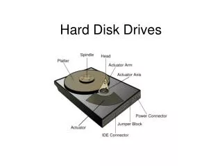
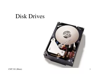
Mechanically Speaking • Individual Disks, or Platters • Read/Write heads for each platter on actuator arms controlled by servo motor
At arm’s length • Platters are made of aluminum (hence “hard”) with magnetic media on each face. • The read/write heads “float,” or fly, above the surface of disk Read/Write head Fingerprint Media Aluminum
Data Encoding • We use “flux reversals” to signal a 1 or 0 • This is serial (one bit at a time)
Encoding Methods • Old methods: • FM. Frequency Modulation. Bit/Timing/Bit • MFM. Modified FM. Timing after two 0’s • Current methods: • RLL. Run Length Limited. Use short patterns to represent longer ones. 1991 • PRML. Partial Response Maximum Likelihood
Even more capacity • Stand the magnets on their nose • Perpendicular recording: • Used in iPod, and starting to appear for us.
Moving the arms • Stepper motors • Moves arm in fixed amounts (angular) • Data transfer errors as motor wears • Thermal expansion errors • Needed to “Park” the heads over non-data area before moving drive • Floppy drives still use stepper motors
Moving the arms • Voice coil “motor” • Same idea as the cone of a speaker
Voice Coil • Don’t need to “Park” the heads – they move automatically when power removed. • No contact means no wear, no thermal issues, faster movement • Can use one disk surface for positioning
Data Storage • Where will we put the data we want to store? • How will we know how to get back to that data the next time we want to use it? • It turns out that three values will get you positioned at a known spot. These three values are called…
Geometry • Every model of drive uses a different geometry – total frustration years ago • Three values used today: Heads, Cylinders and Sectors per track (CHS). • Two obsolete values: write precomp and landing zone
Heads • The number of heads (and thus the number of platters) the drive has installed • Two heads per platter – but a drive may use one head for its own use; thus we can have an even, or odd, number of heads for data use.
Cylinders • Also called “Tracks” • If we hold the heads still for a moment and allow the platters to spin, the heads will describe a circle Track platter Lots of tracks: use concentric circles (same center point, different diameter) Platter !
Sectors per track • Slice each disk like a pie – each part of a track is called a sector • A sector holds 512 Bytes (or less) of data
The other two • Write Precompensation Cylinder. Where the data encoding distance changed • Landing Zone. Where the heads went when parked.
Talk to the drive • IDE. Integrated Device Electronics. Move the controller circuitry to the drive. 1990 Replaced two separate pieces that were joined by two ribbon cables.
Talk to the drive, cont. • SCSI – Small Computer System Interface, that discussion is coming shortly…
IDE/ATA • Started showing up around 1990 • Originally just parallel interface, now called PATA – Parallel AT Attachment Interface • SATA – Serial AT Attachment Interface. Started showing up around 2003
PATA or IDE drives • Western Digital and Compaq in 1989 • Gave it to ANSI for formal specification • Used the AT BIOS routines and two drives up to 504MB (when a 10 MB was huge!) • Enhanced IDE (EIDE) in 1991 • Ultra- DMA in about 1994
Physical Connection • Here is the back of a disk drive: Jumper Block 40-pin connector Pin 1 Power connection
The other end • “Controllers” (really just pin connectors)
Connecting Cable • 40 pins and either 40 wires (Ultra ATA-33) or 80 wires (+40 grounds) for ATA-66,-100 and -133
Setting the Jumper • Because we can connect two drives, we need to distinguish between the two • “Master” and “Slave” – Typically we boot from Master drive, but could boot from Slave drive
Jumper Location • Older drives had jumper location in different places on controller card: Smaller than jumpers on motherboard
Another Drive • Jumper location on back of drive
If I don’t know… • Look around on the drive for jumper block • Read the label • Go to drive manufacturer’s web site for information • Some drives have a “Single” setting that you have to use if only one drive installed
On a 40-wire cable ONLY • Drive to connector is optional:
ATAPI • Advanced Technology Attachment Packet Interface, part of ATA-2 per Michael • Allows CD, DVD and Zip drives to connect to IDE cable(s) and controller • Began at about 24x CD • Scott Mueller says it showed up in ATA-4 • Higher capacities, support for two more devices (total of four)
Translation, ATA-2 • Translates cylinder and head values • We know that 16*2 (32) is the same as 4*8 (32, again), so we fib to CMOS what the “Logical” CHS values are, not the “Physical” values • BIOS uses logical values, controller converts to physical values • Use “extra” bits to allow up to 256 heads
Sector Translation Shift numbers by 16x
ATA-3 • Added S.M.A.R.T. – Self-monitoring, Analysis, and Reporting Technology • In theory, it is to help predict when drive will fail, but it generally is not used
ATA-4 • Introduced Ultra-DMA (does not use the old DMA controller) • Introduced the 80-wire cable (still 40 pins) – optional usage meant no usage • UDMA/33 – 33 MBps max transfer rate • 1996 – 1998 timeframe
LBA • Logical Block Addressing • Divide total number of sectors (C*H*S) to get “new” C, H values leaving S=63 • (1024)(256)(63)(512)=8.4 GB • Both the BIOS and hard disk drive have to be capable of LBA
INT 13h Extensions to LBA • Breaks the 8.4 GB limit • Collect a lot of the bits (plus some previously unused bits) to allow 2^28 address bits • Max drive size moves up to 137 GB • Around 2000
ATA-5 • UDMA/66 – 66 MBps • 80-conductor cable now mandatory else the drive slows down transfer rate; positions on cable are now standardized • 1998 – 2000 timeframe
More on the cable • ATA/66 requires an 80-wire cable. • Contrary to Michael, you CAN use ’66 drive and ’66 controller with 40-wire cable, it just runs slow but no data loss. • Actually, the BIOS will whimper at you at each startup about the cable.
ATA - 6 • UDMA/100 • LBA addressing from 2^24 to 2^48 sectors which breaks 137 GB limit • 2000 – 2002 • Mechanically, we are still at about 60 MBps from read/write head to controller card (on the drive). Add buffer on drive.
ATA - 7 • Introduced SATA drives (-1 and -2; 150 and 300 MBps) • UDMA – 133; never made it to mass production
Drive Maximums • Prior to 1995 – 528 MB • BIOS CHS (1024,16, 63) limit • Prior to Jan 1998 – 8.4 GB • “Logical” heads to 256 (LBA) • Prior to Sept 2002 – 137 GB • Interrupt 13 (Int13) extensions; feed drive stream of addressable sectors Now no limit with 2^48 bits (up from 2^24) but we stop at 2.2TB
SATA • Fewer wires (7) = thinner cable; Differential signals (+ and – voltage) • Up to one meter long cable (from 18”) • Point to point connection – one device per cable so no Master/Slave issue • Performance is issue: 150 MBps vs. IDE at 133; SATA-II at 300 MBps burst mode SATA III at 600MBps • Host Bus Adaptor – where SATA plugs in 20
Data Power
AHCI • Advanced Host Controller Interface • Windows Vista and later • Works with SATA HBA (host bus adapter) • Makes the drive show up in Computer • Enables native command queuing; disk optimization feature
SCSI • Small Computer System Interface • 1970’s by Shugart • Uses a “chain” approach – device to device to Host Adapter/Controller • Can be internal (68-pin) or external (50-pin); newest use 68-pin external • Apple (older) used 25-pin connector (SCSI-1)
SCSI ID • Use a number to identify devices on a link • Can be any number (0-7 for SCSI-1); 0-15 for SCSI-2 or -3 • Host adapter usually set to 7; boot device set to 0
Termination • Easy – both ends of the SCSI chain • Most devices have termination built in; can cause fits getting termination correct • Do it wrong and device(s) won’t show up
Configuring CMOS • At first, we had to know, then type in, the CHS values for a drive – lots of hassle • Today, CMOS will get its information from the drive automatically – even SATA drives
Drive Types • Rather than Cylinders, Heads and Sectors numbers, use Types • We worked our way up to 46 different types, Type 47 was “User Defined” and we were back to CHS values