Download
1 / 12
250 likes | 637 Views
Real-time monitoring and control of the drilling process. WITSML SIG, Paris May 2007. At the well site: avoid generating problems by enforcing drilling operations within safe guards. Support organization: detect and diagnose potential problems as early as possible.

E N D
Real-time monitoring and control of the drilling process WITSML SIG, Paris May 2007
At the well site: • avoid generating problems by enforcing drilling operations within safe guards • Support organization: • detect and diagnose potential problems as early as possible Well construction operation challenges • 15% to 30% of drilling operations is spent in non productive time • Small problems can escalate in very costly situations (formation fracturing mud losses cannot run casing technical sidetrack) DrillScene Drilltronics
Drilltronics Summary • Objective: • reduce non-productive time during drilling operations by avoiding influx from formation, formation fracturing and collapse, poor hole cleaning, drill-string damage • Principle: • it is a drilling control system based on Cyberbase from National Oilwell Varco (NOV) which controls actively the draw-work, top-drive and mud pumps to account for the dynamic behavior of the well during drilling operations • Usage: • Used by the driller and assistant driller at the rig site • Project: • Started in 2003 and sponsored by Statoil and ENI and realized by IRIS and NOV • Status: • All functionalities have been successfully tested on a test rig (Ullrigg) in May 2006 • Will be tested on Statfjord C (North Sea) Sept 2007
Objective: Limit acceleration/deceleration and velocity during tripping operations to avoid damaging open hole section due to swab/surge effects. Principle: Define a top and bottom limits for hook movement (typically from 1m to 30m) Use at any time the minimum of the machine limits and the well limits for the acceleration/deceleration and velocity The well limits are calculated in real-time by Drilltronics and varies with the mud condition and the bit depth. Function: Activated via key pad (Trip limits on) Normal use of joystick (but acceleration/deceleration and velocity controlled by maximum limits) Drilltronics drillstring velocity limits
Objective: Progressive startup of mud pump accounting for gel, temperature and fracturing pressure in open hole. Principle: If air in drill-pipe, use fill pipe function until a maximum SPP is reached. Increase pump rate in a stepwise way with guaranteed minimum waiting time between each plateau. Two startup modes: Stepwise: used to start pump by increments when final flowrate is not yet decided Resume: used to start pump to a pre-defined flow rate Function: Key pad activated (additional options to standard pump control functions) Drilltronics Pump startup
Drilltronics Architecture (next version) • WITSML • OPC • SOAP, WSDL Drilltronics core system Drilling Performance Calculation Pump Startup Calculations Tripping limits Calculation 3.rd party GUI Client Dedicated WITSML server Web Service 3.rd party Models 3.rd party Data Machine Control System
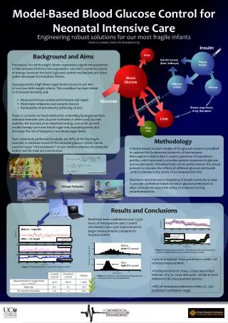
DrillScene Summary • Objective: • Continuous assessment of drilling performance and risks. • Early warning in real-time to support drilling operations. • Principle: • Use a WITSML server as the source of real-time data • Continuous modeling of the mechanical and hydraulic situation in the complete wellbore and drill-string • Continuous calibration of mechanical and hydraulic models to match measurements • Alarm generation when hole conditions closed to or exceeding limits • Usage: • Used by drilling engineers, operation geologists • Project: • Started in 2005 and funded by Norsk Hydro and ENI • Status: • Tested at Norsk Hydro on Grane (North Sea), January - February 2007
DrillScene Architecture Database Rig data WITSML client Web service Well response modeling and calibration (1s) Drilling operation margin calculations (2min) Forecast estimation (15 to 30 min) Server Clients
Downhole ECD Modeled In annulus Downhole ECD Measurement DrillScene Functionalities • Complete and continuous description of hydraulic regime in wellbore and drillstring • Calibration of hydraulic model based on pump pressure and downhole ECD • Monitoring of open hole ECD with regards to geo-pressure margins • Monitoring of tank volume to detect gain or loss • Continuous calculation of thermal exchange and effects on wellbore stability • Monitoring of torque/drag limits along drillstring at any time • Account for hydraulic effects on mechanical results • Calibration of mechanical model when bit is off bottom • Monitoring of mechanical friction evolution has an indicator of poor hole cleaning
Head Quarter’s WITSML Server Kongsberg Intellifield Head Quarter’s DrillScene Server for Grane Grane’s WITSML Server Inteq DrillScene on Grane’s engineers desktops (7 users) DrillScene test at Norsk Hydro: Grane
Transform data into dynamic safe guards to control drilling machineries at the rig site Drilltronics Transform data into dynamic alarms to support decision making for the support organization DrillScene Summary Use WITSML as a transfer protocol