Download
1 / 27
270 likes | 397 Views
This summary highlights the key points from the mini-workshop on real-time orbit control held on October 6, 2003, focusing on its significance in maintaining beam stability during various operational phases at the LHC. The workshop covered the deterministic nature of the orbit control system, the unique challenges posed by the LHC's large-scale, distributed nature, and the critical role of various parties involved, including the Beam Position Monitors, communication servers, and orbit corrector controls. Detailed presentations and further information are available at the provided link.

E N D
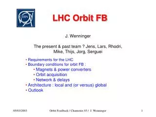
Real-time orbit control @ the LHC Summary of the mini-workshop held Oct 6th 2003 J. Wenninger AB-OP-SPS With emphasis on control aspects Details of all presentations are available on : http://proj-lhcfeedback.web.cern.ch/proj-lhcfeedback/workshop/workshop.htm AB-CO TC / J. Wenninger
Real-time orbit control : what’s that ? The aim of real-time orbit control system is to stabilize the orbit of the LHC beams during ALL operational phases within the required tolerances. It is a real-time system in the sense that the system must be deterministic – this very important during critical phases. The LHC system is ‘unique’ because it is distributed over a large geographical area and because of the large number of components. Very very schematically - we have 5 players : BPM system Network ‘Controller’ Network PC system Beams AB-CO TC / J. Wenninger
People • The partys that are inlvolved : • BDI : beam position system • PC : orbit corrector control • CO : communication, servers, ‘controls infrastructure’ • OP : main ‘user’ Core-team for prototyping work at SPS • BDI : L. Jensen, R. Jones BPM HW & Readout • CO : J. Andersson, M. Jonker Server, PC control • OP : R. Steinhagen, J. Wenninger Algorithms, FB loop, measurements • But also : M. Lamont, Q. King, T. Wijnands, K. Kostro and others AB-CO TC / J. Wenninger
Orbit control @ the LHC • Requirements : • Excellent overall control over the orbit during all OP phases. • RMS change< 0.5 mm– for potential perturbations of up to20 mm. • Tight constraints around collimators (IR3 & 7), absorbers … : • RMS change < ~50-70 mm for nominal performance. • ‘New’ and very demanding requirement from the TOTEM exp. : • Stability of ~ 5 mm over 12 hours around IR5. Main problem : not sure the BPMs are that stable in the first place. • EXPECTED sources of orbit perturbations : • Ground motion, dynamic effects (injection & ramp), squeeze. • Mostly ‘drift- or ramp-like’ effects. • frequency spectrum is < 0.1 Hz AB-CO TC / J. Wenninger
Limitations from power converters & magnets • There are 250-300 orbit corrector magnets per ring and per plane (mostly cold). • SC orbit correctors : • Circuit time constants : t 10 to 200 s (arc correctors ~ 200 s). For comparison, in the SPS : t 0.5 s • EVEN for SMALL signals, the PCs are limited to frequencies ≤ 1 Hz. At 7 TeV small means really small : ~ 20 mm oscillation / corrector @ 1 Hz. Warm orbit correctors : only a few / ring • Circuit time constants t ~ 1 s PC can run them > 10 Hz. • But there are too few of them to make anything useful with them ! • PCs will limit correction by the FB to frequencies ≤ 1 Hz ! AB-CO TC / J. Wenninger
Real-time… Real-time control implies deterministic correction / control stable delays (at least within some tolerances) sampling • Digital loop performance depends on : • Sampling frequency fs • Delay • As a rule of thumb, given the highest frequency fpmax at which the FB should perform well, • fs > 20-30 fpmax • i.e. fpmax = 0.1 Hz fs ~ 3 Hz expected ‘noise’ = 1 Hz fs ~ 30 Hz to reach the PC limit Delay < (1/ fpmax) 0.05~ 50-500 ms I recommend to use the PC limit of 1 Hz as design target and not the expected noise : gives margin + best use of HW ! AB-CO TC / J. Wenninger
RT feedback building blocks + FB controller Correction algorithm Reference Network PC + magnet - Network BPM Beam(s) Each component has its own characteristic transfer function that must be know to design the controller. “Noise” • This RT loop spans the entire LHC machine. • For good performance : • the reliability of each component must be adequate. • the delays must be ‘short’ ~ O(100 ms) and stable. AB-CO TC / J. Wenninger
FB FB FB FB FB FB FB FB FB Global architecture Local / IR • reduced # of network connections. • less sensitive to network. • numerical processing faster. • … • less flexibility. • not ideal for global corrections. • coupling between loops is an issue. • problems at boundaries. • .. • Central • entire information available. • all options possible. • can be easily configured and adapted. • … • network more critical : delays and large number of connections. • … Preferred !! For the moment… IR IR IR IR IR IR IR IR IR IR IR IR IR IR AB-CO TC / J. Wenninger
Beam Position Monitors • Hardware : • 500 position readings / ring / plane ~ 1000 BPMs for the 2 rings • Front-end crates (standard AB-CO VME) are installed in SR buildings • 18 BPMs (hor + ver) 36 positions / VME crate • 68 crates in total 8-10 crates / IR • Data streams : • Nominal sampling frequency is 10 Hz – but I hope to run at 25 Hz… > 100 times larger than the frequency of fastest EXPECTED CO perturbation. • Average data rates per IR : • 18 BPMs x 20 bytes ~ 400 bytes / sample / crate • 140 BPMs x 20 bytes ~ 3 kbytes / sample / IR @ 25 Hz – from each IR : Average rate ~ 0.6 Mbit/s Instantaneous rate ~ 25 Mbit/s (1 msec burst) 40 ms AB-CO TC / J. Wenninger
More on BPMs • An alternative acquisition mode is the multi-turn mode : • For each BPM one can acquire up to 100’000 turns of data / plane. • The acquisition itself does not interfere with RT close orbit, but readout + sending to the user does !! Data volumes : • 100’000 x 2 (planes) x 18 (BPMs) x 4 bytes ~ 16 Mbytes / crate • This data must be extracted without interfering with RT closed orbit. • There are even proposals to ‘feedback’ at 1 Hz on machine coupling… with such data (only 1000 turns !) : • Per IR : 10 x 8 x 16/100 Mbit/s ~ 10 Mbit/s We must carefully design the readout to prevent ‘destructive’ interference of other ‘BPM services’ with RT closed orbit ! AB-CO TC / J. Wenninger
LHC Network • What I retained from a (post-WS) discussion with J.M. Jouanigot • It has lot’s of capacity > 1 Gbit/s for each IR. • It has very nice & very fast switches (ms switching time). • It has redundancy in the connections IR-CR. • Is it deterministic ? • It is not - but delays should be small (< 1 ms), and stable if the traffic is not too high. • All users are equal – but 2 network profiles are available in case of problems. • With the SPS network renovation, we will be able to test a network that looks much more lHC-like in 2004. • I suspect that as long as we do not know details on data rates, it is difficult to make precise predictions for the LHC. AB-CO TC / J. Wenninger
‘Controller’ • Main task of the controller / central server(s) : • Swallow the incoming packets (~ 70 / sampling interval). • Reconstruct the orbit & compare to reference orbit. • Calculate (matrix multiplication … or more) new deflections. • Apply control algorithm to new and past deflections. • Verify current & voltage limits on PCs. • Send corrections out… Other tasks : • Monitor HW status (BPMs & correctors), feed back on response matrices. • Get beam energy & machine state info ( algorithm, optics, reference orbit…). • Logging & post-mortem. • Interaction with operation crews (ON, OFF, parameters…). The controller will (most likely) consist of a number of threads that will be running on a dedicated ‘machine’ and that need some form of RT sheduling and synchronization ! AB-CO TC / J. Wenninger
WorldFip Gateway 1 2 3 30 FGC FGC FGC FGC PC PC PC PC PC control Architecture : • Each PC is controlled by one Function Generator Controller (FGC). • Up to 30 FGCs (PCs) per Worlfip bus segment. • 1 gateway controls a given Worldfip segment. • Orbit correctors are accessed over ~ 40 gateways. Timing & access : • The WorldFip bus is expected to run @ 50 Hz – 20 ms cycle. the FB sampling frequency must be fs = 50 Hz / n n=1,2,3…. • The delay (WorldFip + PC set) is ~ 30-40 ms. • Present idea is to send all settings to some ‘central’ PO gateways that will dispatch the data to the lower level gateways & Worldfip. AB-CO TC / J. Wenninger
PC Gw PC Gw PC Gw PC FE PC FE PC FE PC FE WF WF WF WF Schematically… BPM FE BPM FE Present architecture, as seen by the parties that are involved FB ‘servers’ PO gateways to hide HW details from the clients Remove this layer ? AB-CO TC / J. Wenninger
Delays Estimated delays – in ms : • BPMs 5-10 • Network / inbound 1 • Packet reception 30 • Correction 10-40 • Packets out 10 • Network / outbound 1 • PC control 30-40 • Total 80-120 ms • Just acceptable if you consider the PC limits of 1 Hz. • For a 25 Hz sampling rate, this is already > 1 period ! AB-CO TC / J. Wenninger
BPM Controller WF ‘tick’ PC Synchronization Constant ! • All BPM crates are synchronized via BST to 1 turn. • All PC WF segments are synchronized (GPS). • Synchronize RT acquisition and WF segments to maintain stable delays. AB-CO TC / J. Wenninger
Orbit drifts in the “FB perspective” Consider : • FB sampling rate : 10 Hz • BPM resolution : 5 mm (~ nominal LHC filling) • Tolerance : 200 mm (injection/ramp), 70 mm (squeezed, physics) Compare orbit drift rates in some ‘typical’ and most critical situations.. Phase Total drift/ drift/ No. samples total duration FB interval to reach tolerance Start ramp2 mm / 20 s 10 mm20 (‘snapback’) Squeeze20 mm / 200 s 10 mm7 Physics4 mm / hour 1 mm70* (LEP, pessimistic) Note : those are approximate numbers, but they give an idea of the ‘criticality’ of the communications. (*) : not for TOTEM… AB-CO TC / J. Wenninger
What happens if we lose a sample ? • During the ramp and squeeze phases : • Not nice, but not yet death – we have a small ‘margin’. • In collisions (not for TOTEM !!) , during injection : • Most likely nobody will notice (except the FB itself), • provided we hold the latest settings. • If conditions are similar to LEP, we can afford to loose a few samples at 7 TeV. • We can also rely on reproducibility to feed-forward average corrections from one fill to the next (only ramp & squeeze) may reduce the workload on the FB by ~ 80% - but not guaranteed ! we become less sensitive to packet losses ! • We must keep in mind that : • Packet losses remain a hassle and require more conservative gain settings ! • We cannot tolerate to have long drop-outs (> 500 ms) in critical phases. • Loosing a front-end is also an issue - it is more complex to handle than a lost packet ! AB-CO TC / J. Wenninger
BA5 BA5 PCR bpl50s SPS network abcmw1 SPS network m2sba5 BPM PCs (ROCS) Control server SPS prototyping in 2003 • BPMs : VME crate with LHC ACQ cards ~ identical to LHC, but only 4 BPMs (6 in 2004). • Communication: • BPMs Server : UDP (and later CMW / TCP) • Server PCs : UDP • Central control server for correction, gain control, data logging… • Maximum sampling rate pushed to 100 Hz ! • Present ( ‘old’ ) SPS network was a problem – • ‘frequent’ packet losses. • sometimes important delays (>500 msec). An extremely valuable exercise – a lot of time was spend testing the system on the LHC beams. AB-CO TC / J. Wenninger
And it worked …very well ! BPM Reading (mm) feedback off 450 GeV feedback on Time (ms) ramp injection at 26 GeV feedback on (zoom) ~ measurement noise !! AB-CO TC / J. Wenninger
Looking back @ LEP / I • Although the issues at LEP & LHC are of a different nature, one can learn from LEP : • No real-time orbit acquisition at LEP. • Very strict orbit control required to achieve best luminosity. • Orbit drifts were due to slow ground motion & low-beta quad movements. • During ‘physics’ (i.e. stable collisions) the orbit was stabilized by a feedback. • FB parameters : • Sampling period ~ 15 and 120 seconds. • Non-deterministic, variable delay > 5 seconds. • Corrections were triggered above a threshold : ~ 50 to 200 mm rms. • FB performance : • It had no problem to stabilize the orbit to < 100 mm (if desired !). • We regularly operated with 1 to 3 missing BPM FEs (power supplies…) • no incidence on performance – thank you GLOBAL FB ! Since the same tunnel will host the LHC, there is a fair chance that the LHC beams will exhibit similar drifts in physics. But you are never 100% sure & and LEP was not critical for beam loss ! AB-CO TC / J. Wenninger
Looking back @ LEP / II • The ramp & squeezewere the actual machine efficiency killers : • A large fraction of beams that went into the ramp never made it into physics. • The culprits : • Tune control corrected from 1997 onwards by a real-time tune FB. • Orbit control : remained a problem until the last day ! • The problem : • Orbit changes in R & S were large (many mm rms). • The orbit changes were not sufficiently reproducible (long access…). • Feed-forward of corrections was not sufficiently predictable. • Ramp commissioning and cleaning was very difficult. A 1-2 Hz orbit FB would have cured all our R & S problems ! I think that it is in the ramp and squeeze phases that the orbit FB will be most useful and critical for the LHC ! Again, LEP survived because beam loss was no isssue ! For the LHC we have a chance to anticipate ! AB-CO TC / J. Wenninger
Conclusions • The importance of an orbit FB for the LHC was recognised at an early stage of the LHC design. • As a consequence both BPM and PC systems were designed with RT capabilities. • The RT orbit system must be commissioned at an early stage of the machine startup in 2007 – possibly before we first ramp the beams. • With the SPS we have a valuable (although limited) test ground for ideas and implementations – in particular for controls issues. • We still have some time, but there are number of items to be tackled and some design choice to be made. AB-CO TC / J. Wenninger
Hist list of issues … as I see / feel them at the moment 1 - Data collection from many clients ***(*) Delays, reliability…. 2 - Network AND front-end availability *** Packet loss rate, delays… 3 - RT operating systems & sheduling ** The SPS tests were based on fast response, not determinism ! AB-CO TC / J. Wenninger
Future efforts Operating system & process sheduling : • Interference RT tasks & heavy data transfer in BPM Front-ends. • Tests possible with SPS setup – 2004. • RT scheduling on orbit server(s) side. • Re-design the SPS prototype with LHC oriented & re-usable architecture – 2004. Network / data collection : • Check out the new IT network in the SPS in 2004. • Tests in the IT lab / SM18 (traffic generators…). • Question : do we need a dedicated network ? • The need is not 100% obvious to me, but if we get, we take it ! • Must span ~ all the LHC ! • Data collection tests. • We must ‘convince’ ourselves that a central server can swallow 70 packets @ 25 Hz over > 24 hours without crashing & with adequate response time. AB-CO TC / J. Wenninger
Future efforts / open questions II Architecture and overall optimization : • Optimization of BPM layout in FEs, number of correctors… may reduce the number of clients by 20 or so. • Accelerator simulations of faults… 2004-2005… Synchronization : • Synchronization scheme for BPMs, FB server & PCs. SPS tests : 2004 • Continue studies in the SPS (Network, loop, BPM Front-end…). • ‘Interaction’ FB & proto-type collimators in LSS5. AB-CO TC / J. Wenninger
It’s not all orbit… Eventually we also have to deal with : • Q (Tune) feedback. • Chromaticity feedback ? • Feed-forward of multipoles from SM18 reference magnet. Those systems are simpler because : • 1 ‘client’ that generates data & much smaller number of PCs. …and more delicate because : • Measurement rates depend on beam conditions (Q, Q’). • Measurement number / fill may be limited – emittance preservation. • Feed-forward is intrinsically more tricky. So far little controls activity… Next event : workshop on reference magnets / feed-forward in March 2004 by L. Buttora, J. Wenninger et al. – to be confirmed. AB-CO TC / J. Wenninger