Download
1 / 43
430 likes | 568 Views
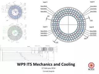
WP9 ITS Mechanics and Cooling. 17 February 2014. Corrado Gargiulo. WP9 Objective 1. Finalization of IB geometry (inputs from WP1 and WP2) and layout (with WP6 and WP10). Finalization of OB geometry (with inputs from WP1 and WP2) and layout (with WP7-WP8 and WP10).

E N D
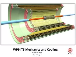
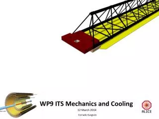
WP9 ITS Mechanics and Cooling 17 February 2014 Corrado Gargiulo
WP9 Objective 1 • Finalization of IB geometry (inputs from WP1 and WP2) and layout (with WP6 and WP10). Finalization of OB geometry (with inputs from WP1 and WP2) and layout (with WP7-WP8 and WP10). • BP radius OR=18mm Vs 19.8mm (WP1,WP2 and MFT) • Layer 0 radius Distance from BP wall • Middle Layer radius TDR6/TDR7 • Stave width Chip size i.e. Layer 0 radius, FPC layout • Stave length Layer radius, Power regulator
BP Outer Radius =……… (19.8mm TDR) • Layer 0 Mid Radius =……… (23.38mm TDR)
19.8BeamPipe (BP) layout at C-side with an Outer Radius (OR) 19.8 mm hasbeenfinalized and proposed to MFT, with a possible disks distributionthatshould match MFT requirements. ITS/MFT InnerEnvelope OR 21.8mm BP‐ITS clearence 2mm; BP‐MFT clearence 2mm BP alignment tolerance 3.3mm 18.0BP OR reduction from 19.8 to 18mm imposes severe constraints on the BP installation tolerances that requires a feasibility study. Providing the layout abovementioned (19.8) isvalidated by MFT group, the BP OR of 18mm willnot be anymore a requirement for MFT. ITS: BP OR reductionto 18mm willnotbringevidentgains, seetodaypresentation from Andrea (WP1), Iouri (WP2). ITS/MFT InnerEnvelopeOR 20.0mm BP‐ITS clearence 2mm ; BP‐MFT clearence 2mm BP alignment tolerance 1.5mm 19.0ifboth ITS and MFT willnotneed a BP OR 18mm we can assume ITS and MFT layout based on a 19.8mm BP OR (ITS/MFT InnerEnvelopeOR 21.8mm). A compromise on the BP OR, 19mm, could be thenconsidered. Thiswillallow to enlarge the clerancebetween BP and ITS/MFT envelope from 2mm to 3mm and keep the installationtollerance of the BP at 2.5mm. Thisproposalisbased on the factthat the distance of beampipe to the first layer of the ITS ismuchlessimportantthanassumedearlier. ITS/MFT InnerEnvelopeOR 21.8mm BP‐ITS clearence2.8mm; BP‐MFT clearence2.8mm BP alignment tolerance 2.5mm
19.8 (TDR) 18.0 Chip width 14,00mm 23.38-19.8= 3.58mm 21.36-18= 3.36mm distance layer-0 (mid) from Beam Pipe Outer wall 19.0 Reducedbeam pipe radius by 0.8mm No change in the ITS layersradius (TDR) Solution endorsed by this ITS plenary meeting See Andrea presentation R 19,0 23.38-19.0= 4.58mm
Beam pipe layout: development of the two options 18mm, 19.8 inner radius 18mm outer radius 19.8 mm outer radius
η= -3,7 (3°) 5 4 3 2 Beam pipe layout and support vs MFT: Proposal sent to MFT, under evaluation… 1 0
TDR 7 • Increasenumber of stave • Increasenumber of modules per stave • Increasestavelength
TDR 6 Pseudo-rapidity coverage The pseudorapidity coverage of the detector layers refers to tracks originating from a collision at the nominal interaction point (z= 0) -1.39 -1.51 -1.31 -1.51 -1.39 -1.51 -1.34 -1.50 TDR 7
TDR 6 763 (1526) 450 (900) BP SUPPORT η= -1,22 (32.8°) MFT disks η= -2,5 (9.4°) η= -3,7 (3°) beampipe 569 688 455 493 531 768 78 430 900 absorber STAVE LENGHT 1526, 900
812 763 (1526) 548 (1096) BP SUPPORT MFT disks beampipe 569 688 455 493 531 768 430 900 STAVE LENGHT 1526, 1096 absorber TDR 7
Stave width=…… (15mm TDR) • Chip size i.e. Layer 0 radius, • FPC layout
Stave width=14mm Chip width 14.0mm neededfor BP 18mm The same chip adopted on the outer layers
IB Stavewidth=15,7 mm FPC width15,7mm Chip 15mm (TDR) FPC
OB Stavewidth=15,7 mm FPC width 15,7mm 1,41 TBD cold plate displacement to re-open the gap from 1.41 to 2mm? Electronics components on the FPC will close this gap
IB Stave length=320mm needed for IB 4th layer Beingconsidered in TDR7. 300 320
IB Stave length=290mm (TDR) chip 9.6 270.8 290
OB Stave length module module 15.7 OL 14.85 ML 1502 OL - 870 ML
Summary (TDR, endorsed in this meeting) • BP outer radius18/ 19.8/19 • Layer 0 mean radius23.38/21.36(BP18) • Middle Layer radius TDR6 / TDR7 • Stave width 14 (BP 18)+1(FPC) / 15+1(FPC) • Stave length (cold plate) IL 320 (4th IB layer) • IL 290=9.6+270.8+9.6 • ML 870= 14.85+840.3+14.85 1066 • OL 1502=15.7+1470.6+15.7
stave Inner barrel
Inner Barrel stave IB status QULIFICATION MODULE PRODUCTION (FINAL QUALITY) • Production of new stave with high dimensionalaccuracy • moulds accuracy needs correction next DEVELOPMENT TEST (on EM) • Dimensional next sag • Thermal test OK • Thermoelastic test on going • Stiffnesstest sag <10 µm (~7µm ) • Vibrational test >100Hz 167 Hz
Inner Barrel stave On going Alternative option under investigation to further improve stiffness and thermo-elastic stability Change of Carbon fleece with K13D2U (same weight) 45µ 20µ 30µ (30µ) 70µ 45µ 45µ 20µ 26
End wheels Inner barrel
Inner Barrel end-wheels status Proto produced based non EM design next Production of set-pins and stave connectors and dimensional check Definition of end-wheel QM design and assembly procedure: joint with WP6 Feed through for cable and pipes See Antonello presentation for FPC and cable layout
Stave Outer barrel
Outer barrel stave status ENGINEERING MODULE PRODUCTION • Produced Stave Full length Proto Baseline OK • Cold plate 2 pipes ID=2.67mm full length for WP8 DEVELOPMENT TEST On spaceframe (Carbon fiber K13 D2U) • Bending test &FEA sag ≈95µm • Vibrationaltest 1st freq=51Hz; dynamicresponseongoing On coldpalte • Thermoelastic test αexp ~ 12 x 10-6 K-1 • Thermal (150 and 300 mW/cm2), hydraulic test Ok
Outer barrel stave on going spaceframe • Improve stave stiffness by replacing 2 M55j plies with K13D2U. • Full k13 spaceframe has shown to be too brittle • Being prepared, spaceframe M55j baseline • Being prepared, spaceframe M55j with additional layer • Being prepared, spaceframe M55j with two layers K13d2U • Further improvement of stave stiffness: increase stave section, need new mould
Outer barrel stave on going • Production of 1 cold plate 1,5m for WP8 • Production of 1 cold plate 300mm for thermal test Cold plate • Alternative option under investigation to further improve stiffness and thermo-elastic stability • Mould under modification (for ID 2mm), Grenoble • New 2mm ID pipes arrived • K13 form Berkley arrived 45µm 20µ 30µ 30µ ID=2.67mm, wt=0.065mm ID=2.00mm; wt=0.025mm 90µ 70/45µm 45µm 20µ 33
End wheels Outer barrel
Outer barrel end-wheels status EM design 300mm on going Definition of cooling modularity and cooling scheme Definition of electrical and hydraulic connection best location TBD 300mm 300mm next Definition of end-wheel QM design and assembly procedure 300mm 150mm EW
cage on going Study on rails to optimize half barrels closure Reduce half barrel parallel translation to minimum
Structural shell ITS CYSSs MFT service barrel Cage
TPC Cage preliminary MFT service Barrel ITS OuterBarrel ITS InnerBarrel Cage: Dav=1085mm MFT: Dav= 990mm ITS_OB: Dav=908mm ITS IB: Dav= 97mm Total 5-6mm carbon~ 2-2.3%
preliminary Cage ITS IB ITS OB MFT skin ITS Inner Barrel (0.2mm*) core sandwich ITS Outer Barrel (1.2mm*) skin MFTServiceBarrel (1.6*) mm *skins: CFRP X0≈25cm Cage (2-3mm*) core: closedcellfoam X0≈1380cm
Materials on going Development of Material database and CERN standard conformity verification for all mechanical parts • CERNREFERENCE DOCUMENTS: • The Use of Plastics and other Non-Metallic Materials at CERN with respect to Fire Safety and Radiation Resistance- (CERN-IS-41) • Compilationof radiation damage test data, Part I, II, III, IV( CERN 79–04, CERN 79–08 , CERN 82–10, CERN 89–12 ) • “polyimide tubes” • Water absorption and erosionresistancecheckOngoing • “connectors” • Evaluation of best material Macor, Durostom 203 –PEEK vs Accura Bluestone (3d print) Ongoing • “composite ” • Fiber K13C2U received from Eric (Berkley) to be used in the cold plates proto production • Core material: Airex R-82 foam Ongoing • “glue-adhesive ” Adhesive tape (60 µm) 3M 467Mp 200MP received from Eric (Berkley) to be evaluated for Module fixation