Download
1 / 72
830 likes | 1.14k Views
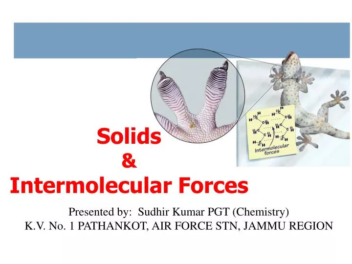
Solids & Intermolecular Forces. Presented by: Sudhir Kumar PGT (Chemistry) K.V. No. 1 PATHANKOT, AIR FORCE STN, JAMMU REGION. Comparisons of the States of Matter. the solid and liquid states have a much higher density than the gas state

E N D
Solids &Intermolecular Forces Presented by: Sudhir Kumar PGT (Chemistry) K.V. No. 1 PATHANKOT, AIR FORCE STN, JAMMU REGION
Comparisons of the States of Matter • the solid and liquid states have a much higher density than the gas state • therefore the molar volume of the solid and liquid states is much smaller than the gas state • the solid and liquid states have similar densities • generally the solid state is a little denser • notable exception: ice is less dense than liquid water • the molecules in the solid and liquid state are in close contact with each other, while the molecules in a gas are far apart 2 Sudhir Kumar PGT (Chem.) KV Chamera -2
Freedom of Motion • the molecules in a gas have complete freedom of motion • their kinetic energy overcomes the attractive forces between the molecules • the molecules in a solid are locked in place, they cannot move around • though they do vibrate, they don’t have enough kinetic energy to overcome the attractive forces • the molecules in a liquid have limited freedom – they can move around a little within the structure of the liquid • they have enough kinetic energy to overcome some of the attractive forces, but not enough to escape each other 4 Sudhir Kumar PGT (Chem.) KV Chamera -2
Properties of the 3 Phases of Matter • Fixed = keeps shape when placed in a container • Indefinite = takes the shape of the container 5 Sudhir Kumar PGT (Chem.) KV Chamera -2
Solids properties & structure
Bonding in Solids • There are four types of solid: • Molecular (formed from molecules) - usually soft with low melting points and poor conductivity. • Covalent network (formed from atoms) - very hard with very high melting points and poor conductivity. • Ions (formed form ions) - hard, brittle, high melting points and poor conductivity. • Metallic (formed from metal atoms) - soft or hard, high melting points, good conductivity, malleable and ductile. Sudhir Kumar PGT (Chem.) KV Chamera -2
Crystalline Solids Determining Crystal Structure • crystalline solids have a very regular geometric arrangement of their particles • the arrangement of the particles and distances between them is determined by x-ray diffraction • in this technique, a crystal is struck by beams of x-rays, which then are reflected • the wavelength is adjusted to result in an interference pattern – at which point the wavelength is an integral multiple of the distances between the particles 8 Sudhir Kumar PGT (Chem.) KV Chamera -2
X-ray Crystallography Sudhir Kumar PGT (Chem.) KV Chamera -2 9
Bragg’s Law • when the interference between x-rays is constructive, the distance between the two paths (a) is an integral multiple of the wavelength nl=2a • the angle of reflection is therefore related to the distance (d) between two layers of particles sinq= a/d • combining equations and rearranging we get an equation called Bragg’s Law 10 Sudhir Kumar PGT (Chem.) KV Chamera -2
n, q, l d Example – An x-ray beam at l=154 pm striking an iron crystal results in the angle of reflection q = 32.6°. Assuming n = 1, calculate the distance between layers Given: Find: n = 1, q = 32.6°, l = 154 pm d, pm Concept Plan: Relationships: Solution: Check: the units are correct, the size makes sense since the iron atom has an atomic radius of 140 pm Sudhir Kumar PGT (Chem.) KV Chamera -2
Crystal Lattice • when allowed to cool slowly, the particles in a liquid will arrange themselves to give the maximum attractive forces • therefore minimize the energy • the result will generally be a crystalline solid • the arrangement of the particles in a crystalline solid is called the crystal lattice • the smallest unit that shows the pattern of arrangement for all the particles is called the unit cell 12 Sudhir Kumar PGT (Chem.) KV Chamera -2
Unit Cells • unit cells are 3-dimensional, • usually containing 2 or 3 layers of particles • unit cells are repeated over and over to give the macroscopic crystal structure of the solid • starting anywhere within the crystal results in the same unit cell • each particle in the unit cell is called a lattice point • lattice planes are planes connecting equivalent points in unit cells throughout the lattice 13 Sudhir Kumar PGT (Chem.) KV Chamera -2
Unit Cells Sudhir Kumar PGT (Chem.) KV Chamera -2
Unit Cells • Three common types of unit cell. • Primitive cubic, atoms at the corners of a simple cube, each atom shared by 8 unit cells; • Body-centered cubic (bcc), atoms at the corners of a cube plus one in the center of the body of the cube, corner atoms shared by 8 unit cells, center atom completely enclosed in one unit cell; • Face-centered cubic (fcc), atoms at the corners of a cube plus one atom in the center of each face of the cube, corner atoms shared by 8 unit cells, face atoms shared by 2 unit cells. Sudhir Kumar PGT (Chem.) KV Chamera -2
Unit Cells Sudhir Kumar PGT (Chem.) KV Chamera -2
c c c c b b b b a a a a Monoclinic a ¹ b ¹ c 2 faces 90° Cubic a = b = c all 90° Tetragonal a = c < b all 90° Orthorhombic a ¹ b ¹ c all 90° c b a Hexagonal a = c < b 2 faces 90° 1 face 120° Triclinic a ¹ b ¹ c no 90° 7 Unit Cells c b a Rhombohedral a = b = c no 90° Sudhir Kumar PGT (Chem.) KV Chamera -2 17
Unit Cells • the number of other particles each particle is in contact with is called its coordination number • for ions, it is the number of oppositely charged ions an ion is in contact with • higher coordination number means more interaction, therefore stronger attractive forces holding the crystal together • the packing efficiency is the percentage of volume in the unit cell occupied by particles • the higher the coordination number, the more efficiently the particles are packing together 18 Sudhir Kumar PGT (Chem.) KV Chamera -2
Cubic Unit Cells • all 90° angles between corners of the unit cell • the length of all the edges are equal • if the unit cell is made of spherical particles • ⅛ of each corner particle is within the cube • ½ of each particle on a face is within the cube • ¼ of each particle on an edge is within the cube 19 Sudhir Kumar PGT (Chem.) KV Chamera -2
Simple Cubic Sudhir Kumar PGT (Chem.) KV Chamera -2 21
Cubic Unit Cells - Simple Cubic • 8 particles, one at each corner of a cube • 1/8th of each particle lies in the unit cell • each particle part of 8 cells • 1 particle in each unit cell • 8 corners x 1/8 • edge of unit cell = twice the radius • coordination number of 6 2r 22 Sudhir Kumar PGT (Chem.) KV Chamera -2
Body-Centered Cubic Sudhir Kumar PGT (Chem.) KV Chamera -2 23
Cubic Unit Cells - Body-Centered Cubic • 9 particles, one at each corner of a cube + one in center • 1/8th of each corner particle lies in the unit cell • 2 particles in each unit cell • 8 corners x 1/8 + 1 center • edge of unit cell = (4/Ö 3) times the radius of the particle • coordination number of 8 24 Sudhir Kumar PGT (Chem.) KV Chamera -2
Face-Centered Cubic Sudhir Kumar PGT (Chem.) KV Chamera -2 25
Cubic Unit Cells - Face-Centered Cubic • 14 particles, one at each corner of a cube + one in center of each face • 1/8th of each corner particle + 1/2 of face particle lies in the unit cell • 4 particles in each unit cell • 8 corners x 1/8 + 6 faces x 1/2 • edge of unit cell = 2Ö 2 times the radius of the particle • coordination number of 12 26 Sudhir Kumar PGT (Chem.) KV Chamera -2
m, V fcc d mass r l V Example – Calculate the density of Al if it crystallizes in a fcc and has a radius of 143 pm Given: Find: face-centered cubic, r = 1.43 x 10⁻⁸ cm, m = 1.792 x 10⁻²² g density, g/cm3 face-centered cubic, r = 143 pm density, g/cm3 Concept Plan: Relation-ships: # atoms x mass 1 atom l = 2r√2 V = l3 d = m/V 1 cm = 102 m, 1 pm = 10-12 m V = l3, l = 2r√2, d = m/V fcc = 4 atoms/uc, Al = 26.982 g/mol, 1 mol = 6.022 x 10²³ atoms Solution: Check: the accepted density of Al at 20°C is 2.71 g/cm3, so the answer makes sense Sudhir Kumar PGT (Chem.) KV Chamera -2
Closest-Packed StructuresFirst Layer • with spheres, it is more efficient to offset each row in the gaps of the previous row than to line-up rows and columns 28 Sudhir Kumar PGT (Chem.) KV Chamera -2
Closest-Packed StructuresSecond Layer • the second layer atoms can sit directly over the atoms in the first – called an AA pattern ∙ or the second layer can sit over the holes in the first – called an AB pattern 29 Sudhir Kumar PGT (Chem.) KV Chamera -2
Closest-Packed StructuresThird Layer – with Offset 2nd Layer • the third layer atoms can align directly over the atoms in the first – called an ABA pattern ∙ or the third layer can sit over the uncovered holes in the first – called an ABC pattern Cubic Closest-Packed Face-Centered Cubic Hexagonal Closest-Packed 30 Sudhir Kumar PGT (Chem.) KV Chamera -2
Hexagonal Closest-Packed Structures Sudhir Kumar PGT (Chem.) KV Chamera -2 31
Hexagonal Closest Packing Sudhir Kumar PGT (Chem.) KV Chamera -2
Cubic Closest-Packed Structures Sudhir Kumar PGT (Chem.) KV Chamera -2 33
Close Packing of Spheres Sudhir Kumar PGT (Chem.) KV Chamera -2
The Indicated Sphere Has 12 Nearest Neighbors Sudhir Kumar PGT (Chem.) KV Chamera -2
The Holes that Exist Among Closest Packed Uniform Spheres Sudhir Kumar PGT (Chem.) KV Chamera -2
The Position of Tetrahedral Holes in a Face-Centered Cubic Unit Cell Sudhir Kumar PGT (Chem.) KV Chamera -2
Cubic Closest Packing Sudhir Kumar PGT (Chem.) KV Chamera -2
Classifying Crystalline Solids • classified by the kinds of units found • sub-classified by the kinds of attractive forces holding the units together • molecular solids are solids whose composite units are molecules • ionic solids are solids whose composite units are ions • atomic solids are solids whose composite units are atoms • nonbonding atomic solidsare held together by dispersion forces • metallic atomic solids are held together by metallic bonds • network covalent atomic solids are held together by covalent bonds 40 Sudhir Kumar PGT (Chem.) KV Chamera -2
Molecular Solids • the lattice site are occupied by molecules • the molecules are held together by intermolecular attractive forces • dispersion forces, dipole attractions, and H-bonds • because the attractive forces are weak, they tend to have low melting point • generally < 300°C 42 Sudhir Kumar PGT (Chem.) KV Chamera -2
Ionic SolidsAttractive Forces • held together by attractions between opposite charges • nondirectional • therefore every cation attracts all anions around it, and vice versa • the coordination number represents the number of close cation-anion interactions in the crystal • the higher the coordination number, the more stable the solid • lowers the potential energy of the solid • the coordination number depends on the relative sizes of the cations and anions • generally, anions are larger than cations • the number of anions that can surround the cation limited by the size of the cation • the closer in size the ions are, the higher the coordination number is 43 Sudhir Kumar PGT (Chem.) KV Chamera -2
Ionic Crystals CsCl coordination number = 8 Cs+ = 167 pm Cl─ = 181 pm NaCl coordination number = 6 Na+ = 97 pm Cl─ = 181 pm Sudhir Kumar PGT (Chem.) KV Chamera -2 44
Lattice Holes Tetrahedral Hole Octahedral Hole Simple Cubic Hole Sudhir Kumar PGT (Chem.) KV Chamera -2 45
Lattice Holes • in hexagonal closest packed or cubic closest packed lattices there are 8 tetrahedral holes and 4 octahedral holes per unit cell • in simple cubic there is 1 hole per unit cell • number and type of holes occupied determines formula (empirical) of salt = Octahedral = Tetrahedral 46 Sudhir Kumar PGT (Chem.) KV Chamera -2
Cesium Chloride Structures • coordination number = 8 • ⅛ of each Cl─ (184 pm) inside the unit cell • whole Cs+ (167 pm) inside the unit cell • cubic hole = hole in simple cubic arrangement of Cl─ ions • Cs:Cl = 1: (8 x ⅛), therefore the formula is CsCl 47 Sudhir Kumar PGT (Chem.) KV Chamera -2
Rock Salt Structures • coordination number = 6 • Cl─ ions (181 pm) in a face-centered cubic arrangement • ⅛ of each corner Cl─ inside the unit cell • ½ of each face Cl─ inside the unit cell • each Na+ (97 pm) in holes between Cl─ • octahedral holes • 1 in center of unit cell • ¼ of each edge Na+ inside the unit cell • Na:Cl = (¼ x 12) + 1: (⅛ x 8) + (½ x 6) = 4:4 = 1:1, • therefore the formula is NaCl 48 Sudhir Kumar PGT (Chem.) KV Chamera -2
Zinc Blende Structures • coordination number = 4 • S2─ ions (184 pm) in a face-centered cubic arrangement • ⅛ of each corner S2─ inside the unit cell • ½ of each face S2─ inside the unit cell • each Zn2+ (74 pm) in holes between S2─ • tetrahedral holes • 1 whole in ½ the holes • Zn:S = (4 x 1) : (⅛ x 8) + (½ x 6) = 4:4 = 1:1, • therefore the formula is ZnS 49 Sudhir Kumar PGT (Chem.) KV Chamera -2
Fluorite Structures • coordination number = 4 • Ca2+ ions (99 pm) in a face-centered cubic arrangement • ⅛ of each corner Ca2+ inside the unit cell • ½ of each face Ca2+ inside the unit cell • each F─ (133 pm) in holes between Ca2+ • tetrahedral holes • 1 whole in all the holes • Ca:F = (⅛ x 8) + (½ x 6): (8 x 1) = 4:8 = 1:2, • therefore the formula is CaF2 • fluorite structure common for 1:2 ratio • usually get the antifluorite structure when the cation:anion ratio is 2:1 • the anions occupy the lattice sites and the cations occupy the tetrahedral holes 50 Sudhir Kumar PGT (Chem.) KV Chamera -2