Download
1 / 28
280 likes | 349 Views
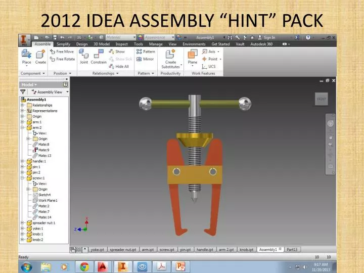
2012 IDEA ASSEMBLY “HINT” PACK. ARM: draw in 2D. Copy / paste this view into Inventor. Whole object takes two extrusions… 1 st Extrusion- take full thickness = 9/16”. 2 nd Extrusion will require a sketch like this…. Yoke in three Inventor steps…. Yoke:

E N D
Whole object takes two extrusions… 1st Extrusion- take full thickness = 9/16”
Yoke: I chose 2D for the sketch; you could make this directly in 3D. Note I did not bother with the hole; do as point center in Inventor.
After extruding the sketch to full height, sketch on top plane and locate the point center. Finish sketch and use 3D Model Hole command to add a ½-13 UNC threaded hole. Be sure to select the thread option (circled in green).
Threaded Holes: To cover the vernacular: ½-13UNC-2A Translates to: : Diameter – Threads Per Inch – Class of Fit =½” Dia bolt –with- 13 threads per inch in the Unified National Course family –with- internal fit (i.e. hole is tapped)
Spreader Nut Two steps in Inventor
Sketch the half section of the nut (minus the hole completely)
Revolve the sketch. When completed, sketch on the top plane and locate center with a point. Add a 3D Model Hole feature using same ½-13UNC-2A specs. Done!
Screw Sketch the full profile and then cut in half.
3D Solids Menu: Look for “Thread” under the Modify tab. Select the face to cut and total length of 3.125.
Need a work plane… Create a sketch on top of the object; need a line from center to quadrant. Create a work plane at the end point of the new line.
Sketch on work plane. Share geometry to get center axis. Locate a 11/32” dia circle and extrude through all.
Done! *Well almost… Got fancy and added a .0625 chamfer on the bottom edge to help “start” the threads.
Pin (Spring Pin) *Catch specs given on bottom of page 3.
Sphere’s Step 1: Sketch a 9/16” circle and bisect it with a line down the middle. Trim off half. “Knobs are 9/16” diameter spheres, with ¼” deep holes for press fit.” -Bottom left of page #3.
Share the sketch for Revolution 1 and create a work plane at the endpoint of the center line. Next, create a sketch on the new work plane.
Project Geometry of the center line onto the work plane and use that point as the center of the 5/16” hole, ¼” deep.
Handle: 5/16”x4” long. Sketch a 5/16” circle and extrude to 4” length.