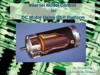
Internal Model Control for DC Motor Using DSP Platform
Internal Model Control for DC Motor Using DSP Platform. By: Marcus Fair Advisor: Dr. Dempsey. Outline. Problem description Objectives Functional Specs Sub-system Overview Software Design . Summary. Design, build, and test IMC (Internal Model Control) system to control a DC motor

Internal Model Control for DC Motor Using DSP Platform
E N D
Presentation Transcript
Internal Model Control for DC Motor Using DSP Platform By: Marcus Fair Advisor: Dr. Dempsey
Outline • Problem description • Objectives • Functional Specs • Sub-system Overview • Software • Design
Summary • Design, build, and test IMC (Internal Model Control) system to control a DC motor • 32-bit TMS320F2812 digital signal processor (DSP) • Design for IMC controller built in Simulink • Input to system uses graphical user interface (GUI) built in Matlab
Preliminary Work • DC Motor block diagrams from Senior Mini-project • Also based on DC Motor Speed Control Demo • M-files to run software • Speed Measurement block in Simulink
Common Problems in Control Systems • Load Changes -Load shaft • Plant Changes -Armature Resistor, Armature Inductor, Rotor Inertia, etc • Power Supply Changes
Build DSP/motor hardware interface Design and build (GUI) Design closed-loop controllers Compare conventional controller results with the IMC method Objectives
Functional Requirements andPerformance Specifications • Closed-loop operation: Determine optimum gains for controllers • Rise time: 20 ms or less • Settling time: 100ms or less • Overshoot: < or = 5% • Steady state error: + or – 5 RPM
Equipment List • GM9236C534-R2 Pittman DC motor • Ezdsp F2812 Board • LMD18200 H-bridge • 3 - SN74LVC4245A voltage shifter • 6-Pin DIP Opto-isolator • 2N2222A BJT • 2 - Diodes • Agilent 30V power supply and HP 5V power supply • Tektronix Oscilloscope
Generation TMS320F281x CPU 1 C28x Peak MMACS 150 Frequency(MHz) 150 RAM 36 KB OTP ROM 2 KB Flash 256 KB EMIF 1 16-Bit PWM 16-Ch CAP/QEP 6/2 ADC 1 16-Ch 12-Bit ADC Conversion Time 80 ns McBSP 1 UART 2 SCI SPI 1 CAN 1 Timers 3 32-Bit GP,1 WD GPIO 56 Core Supply (Volts) 1.9 V IO Supply (Volts) 3.3 V Dsp board technical specs
Delivers up to 3A continuous output Operates at supply voltages up to 55V Low RDS(ON) typically 0.3W per switch TTL and CMOS compatible inputs No “shoot-through” current Thermal warning flag output at 145°C Thermal shutdown (outputs off) at 170°C Internal clamp diodes Shorted load protection Internal charge pump with external bootstrap capability Internal clamp diodes Shorter load protection Internal charge pump with external bootstrap capability H-bridge
Pittman DC Motor Motor Specs Encoder Specs
Software • Matlab -Simulink -main m-files -Gui m-files • Code Composer Studio 2.0 -Auto-code generation -Communication with Dsp board
Design Work • Matlab GUI -Gui m-file • Controller Design Iterations -Proportional Controller -Feed-forward Controller -IMC controller
Feed-forward Controller • Why Feed-forward Controller? • Faster response to command changes than single-loop controllers • Less overshoot: More accurate than single-loop controllers • Better system for Dc Motor control
Feed-forward Equations • C/R = (Gc*Gp + Gp) / (1 + Gp) • Desired C/R = 1.0 • So Gc = 1/Gp to get desired controller • Gain K calculated based on DC gain of plant
Internal Model Controller • IMC uses a plant model for disturbance rejection • More ideal control system • Faster and more robust system
IMC Equations • C/R = (Gc*Gp)/(1 + Gc*Gp - Gc*Gp’) • Desired C/R = 1.0 • So Gc = 1/Gp’ = 1/Gp to get desired controller • Gain K calculated based on DC gain of plant
IMC ControllerActual Results • Hardware didn’t support algebraic loops • Unable to Run IMC from processor
Conclusion • Overall Hardware fully functional • Functional parts of GUI work correctly/ extra features never implemented • All Controllers work in Simulation • Only proportional and feed-forward run off hardware
Feed-Forward Equations C = Gp*(R*Gc + E) E = R - C C = Gc*Gp*R + Gp*R – C*Gp C + C*Gp = Gc*Gp*R + Gp*R C = R*(Gc*Gp + GP) / (1 + GP) C/R = (Gc*Gp + Gp) / (1 + Gp)
IMC EQUATIONS C = E*Gc*Gp E = R – (E*Gc*Gp – E*Gc*Gp’) E + E*Gc*Gp - E*Gc*Gp’ = R E = R / (1 + Gc*Gp - Gc*Gp’) C = (R*Gc*Gp) / (1 + Gc*Gp - Gc*Gp’) C/R = (Gc*Gp) / (1 + Gc*Gp - Gc*Gp’)
Spring Semester Schedule Week Goals 1-7 Build and test single-loop controller, Design Gui layout 8 Build and test feed-forward controller 9-10 Implement IMC with linear model 11 Final testing, final Gui design 12-13 Final documentation