Download
1 / 4
60 likes | 291 Views
This paper is to design PID controller to supervise and control the speed response of the DC motor and MATLAB program is used for industrial application . PID controllers are widely used in a industrial plants because of their simplicity and robustness. The results obtained from simulation are approximately similar to that obtained by practical. Also the dynamic behavior is studied. Manoj Kumar Ranwa | Ameen Uddin Ahmad "Speed Control of DC Motor using PID Controller for Industrial Application" Published in International Journal of Trend in Scientific Research and Development (ijtsrd), ISSN: 2456-6470, Volume-3 | Issue-5 , August 2019, URL: https://www.ijtsrd.com/papers/ijtsrd26599.pdf Paper URL: https://www.ijtsrd.com/engineering/electrical-engineering/26599/speed-control-of-dc-motor-using-pid-controller-for-industrial-application/manoj-kumar-ranwa<br>

E N D
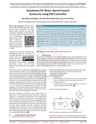
International Journal of Trend in Scientific Research and Development (IJTSRD) Volume 3 Issue 5, August 2019 Available Online: www.ijtsrd.com e-ISSN: 2456 – 6470 Speed Control of DC Motor using PID Controller for Industrial Application Manoj Kumar Ranwa, Ameen Uddin Ahmad Department of Electrical and Electronics Engineering, Al-Falah University, Haryana, India How to cite this paper: Manoj Kumar Ranwa | Ameen Uddin Ahmad "Speed Control of DC Motor using PID Controller for Industrial Application" Published in International Journal of Trend in Scientific Research and Development (ijtsrd), ISSN: 2456- 6470, Volume-3 | Issue-5, August 2019, pp.1164-1167, https://doi.org/10.31142/ijtsrd26599 Copyright © 2019 by author(s) and International Journal of Trend in Scientific Research and Development Journal. This is an Open Access article distributed under the terms of the Creative Commons Attribution License (CC (http://creativecommons.org/licenses/by /4.0) When speed control over a wide range is required, combination of armature voltage control and field flux control is used. This combination permits the ratio of maximum to minimum speed to be 20 to 50. With closed loop control, this range can be extended up to 200. The parameters of the PID controller kp, ki and kd can be manipulated to produce various response[3]. II. PID CONTROLLER: The combination of proportional, integral and derivative control action is called PID control action. PID controllers are commonly used to regulate the time-domain behavior of many different types of dynamic plants. These controllers are extremely popular because they can usually provide good closed-loop response characteristics. Consider the feedback system architecture that is shown in Fig. 1 where it can be assumed that the plant is a DC motor whose speed must be accurately regulated [4]. ABSTRACT This paper is to design PID controller to supervise and control the speed response of the DC motor and MATLAB program is used for industrial application . PID controllers are widely used in a industrial plants because of their simplicity and robustness. The results obtained from simulation are approximately similar to that obtained by practical. Also the dynamic behavior is studied. KEYWORDS: DC motor, PID controller, DC motor armature, DC motor speed response, MATLAB I. INTRODUCTION The DC motors have been popular in the industry control area for a long time, because there good characteristics, for example: high start torque characteristic, high response performance, easier to be linear control…etc. The speed of a DC motor is given be the relationship IJTSRD26599 (1) where V is applied voltage, N is speed , Ia is armature current, Ra is armature resistance and ∅ is the flux per pole[1]. This paper describes the MATLAB/ SIMULINK of the DC motor speed control method namely field resistance, armature voltage, armature resistance control method and feedback control system for DC motor drives [2]. BY 4.0) Fig 1 (a) Fig 1 (b) Feedback system of architecture The PID controller is placed in the forward path, so that its output becomes the voltage applied to the motor's armature the feedback signal is a velocity, measured by a tachometer.The output velocity signal C (t) is summed with a reference or command signal R (t) to form the error signal e (t). Finally, the error signal is the input to the PID controller. (2) @ IJTSRD | Unique Paper ID – IJTSRD26599 | Volume – 3 | Issue – 5 | July - August 2019 Page 1164
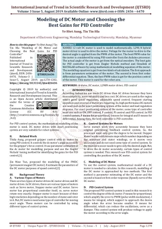
International Journal of Trend in Scientific Research and Development (IJTSRD) @ www.ijtsrd.com eISSN: 2456-6470 III. DC motors have speed-control capability, which means that speed, torque and even direction of rotation can be control at any time to meet new conditions [5] .The electric circuit of the armature and the free body diagram of the rotor are shown in the following fig- 2 [6]. DC MOTOR MATHEMATICS MODEL AND THE CONTROL THEORY: Fig 2 electric circuit of dc motor Let Ra=Armature Resistance, La=Armature self inductance caused by armature flux, ia= Armature current, if= field current, Eb=Back EMF in armature, V =Applied voltage, T=Torque developed by the motor, θ = Angular displacement of the motor shaft, Ј =Equivalent moment of inertia of motor shaft & load referred to the motor, B= Equivalent Coefficient of friction of motor shaft & load referred to the motor. The DC motors are generally used in the linear range of the magnetization curve. Therefore, air gap flux Ф is proportional of the field current i.e. ∅ ∝ if ∅ = Kf if where Kf constant The torque T developed by motor is proportional to armature current and air gap flux T ∝ ia ∅ T = Kf ?? ia ∅ T = ?? ia where ?? is constant . The motor back emf can be written as Eb∝ ?? Eb= Kb ? Eb=Kb?? (3) (4) (5) (6) (7) (8) (9) (10) ?? ( Kb is back emf constant ) If we apply kcl on armature circuit v= Ra ia+La ??? The dynamic equation motor will be (J is moment of inertia B is coefficient of friction ) T=J??? Taking laplace transform of equation(8) (9) and (12). T(s)=K Ia(s) Eb=Kb s ?(?) V(s)= Ia(s) (Ra+LaS)+Eb V(s) - Eb = Ia(s) (Ra+LaS) and T(s)=(Js2+sB)?(?) or T(s)=(Js+B) s ?(?) T(s)=(Js+B) ?(?) T(s)=KIa(s) ?? +Eb (11) ??? +B ?? ?? +TL (12) (13) (14) Fig- 3 Block diagram of armature controlled dc motor @ IJTSRD | Unique Paper ID – IJTSRD26599 | Volume – 3 | Issue – 5 | July - August 2019 Page 1165
International Journal of Trend in Scientific Research and Development (IJTSRD) @ www.ijtsrd.com eISSN: 2456-6470 The transfer function of dc motor speed with respect to the in put voltage can be written as follows G(s) =?(?) Armature controlled dc motor are preferred over field controlled system For small size motor field control is advantageous because only a low power servo amplifier is required while the armature current which is not large can be supplied from an expensive constant current amplifier[7]. For large size motor it is on the whole cheaper to use armature control scheme. Further in armature controlled motor, back emf contributes additional damping over and above that provided by load friction. The combination of proportional, integral and derivative control action is called PID action control and the controller is called three action controllers. Here the proportional part of the control action repeats the change of error and derivative part of the control action adds an increment of output so that proportional plus derivative action is shifted ahead in time. The integral part ads a further increment of output proportional to the area under the deviation line. The combination of proportional, integral an derivative action may be made in any sequence as shown[8]. IV. MATLAB REPRESENTATION AND SYSTEM RESPONSE: Transfer function obtain in equation (15) can be simulate on MATLAB by using practical controller parameter (Kd,Ki and Kp) and DC motor parameter as shown in table -1 and table -2 . ?? ?(?) = (??????)(????)? ???? (15) Fig -4 close loop system of DC motor with PID Controller Parameters: In PID controller there are some parameter (Proportional Gain, Derivative Gain, Filter Coefficient, Integral Gain by varying these parameter response can be change (stability ,error ,rise time etc can be control )[9]. Table -1 Controller Parameters Controller Parameters Tuned Gains Values Proportional Gain Derivative Gain Filter Coefficient Integral Gain DC motor Parameters: Fig -2represent electric circuit diagram of dc motor which consist some practical parameter like Armature resistance (Ra), Armature Coil Inductance ( La), Equivalent Coefficient of friction of motor shaft & load (B) etc .The performance of DC motor( speed of dc motor , Torque of dc motor , current drawn by dc motor etc) can be control by controlling these parameter[10]. Here we are considering practical value of DC motor parameter for better operation of system that given in table-2. Table -2 DC motor Parameters Parameter Armature resistance (Ra) Armature Coil Inductance ( La) Armature Torque Constant (Kt ) Back emf constant (K) Motor Armature Inertia (J ) Equivalent Coefficient of friction of motor shaft & load (B) 100 100 100 1 Value 0.5 1.8*10?? 2.83*10?? 2.83*10?? Vs/rad 20.3 4 Unit Ohm H Nm/A Kgm2 M Fig-5 Close loop system of DC motor with PID controller @ IJTSRD | Unique Paper ID – IJTSRD26599 | Volume – 3 | Issue – 5 | July - August 2019 Page 1166
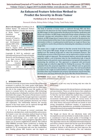
International Journal of Trend in Scientific Research and Development (IJTSRD) @ www.ijtsrd.com eISSN: 2456-6470 Fig. 6 closed loop response of DC motor with PID controller CONCLUSION: From above experimental results we conclude that kp) will have the effect of reducing the rise time and will reduce; but never eliminate the steady-state error, an integral control (ki) will have the effect of eliminating the steady-state error, but it may make the transient response worse .a derivative control (kd) will have the effect of increasing the stability of the system. Here we have used PID controller with the sutable controller parameter as shown in table -2 and response of dc motor drown in Fig-6 which stable and having constant speed 35 rps at (t= 4 sec). REFERENCES: [1]Hang Wu; Weihua Su; Zhiguo Liu, "PID controllers: Design and tuning methods," Industrial Electronics and Applications (ICIEA), 2014 IEEE 9th Conference on, vol., no., pp.808, 813, 9-11 June 2014. [4]Naveen Kumar and Dr. Prasad Krishna, "Low cost data acquition and control using Arduino Prototyping platform and LabVIEW" ,IJSR, Volume 2, Issue-2, February 2013 [5]Purna Chandra Rao et. al., “Robust Internal Model Control Strategy based PID Controller for BLDCM” ,International Journal of Engineering Science and Technology, Volume 2(11), 2010, 6801-6811. [6]Detchrat, et. al. , "IMC-Based PID Controllers Design for Two-Mass System", IMECS 2012 Volume II, Hong Kong. [7]Ibrahim kaya, “IMC based automatic tuning method for PID controllers in a smith predictor configuration" , Science direct, 2004 [8]Farouk Zouari, et.al., “Ädaptive Internal Model Control of a DC Motor Drive System Using Dynamic Neural Network" Journal of Software Engineering and Applications, Scientific Research, 2012, 5, 168-189. [2]S. Poulsen, M. A. E. Andersed 0rsted. “Self Oscillating PWM Modulators, A Topological Comparison”, DTU Automation, Technical University of Denmark Eiehovej, Building 325, 2800 Lyngby, Denmark. [9]Olden. P, “Open Loop motor speed control with LabVIEW”, Southeast Con, Proceedings IEEE, pp. 259- 262, 2001 [3]M. Saranya, D. Pamela, “A Real Time IMC Tuned PID Controller for DC Motor", IJRTE ISSN: 2277-3878, Volume 1, Issue-1, April 2012 [10]Zhen-yu zhao, Masayoshi Tomizuka, and Satoru Isaka , “ Fuzzy gain of PID controller, ” Members, IEEE 1392p . @ IJTSRD | Unique Paper ID – IJTSRD26599 | Volume – 3 | Issue – 5 | July - August 2019 Page 1167