Download

1 / 8
640 likes | 3.39k Views
DC Motor PWM Speed Control. Previous methods of speed control used resistors to drop current/voltage in either the armature or the field. This results in a loss of electrical energy through the control resistor. An electronic alternative that is commonly used is ‘Pulse Width Modulation’.

E N D
DC Motor PWM Speed Control • Previous methods of speed control used resistors to drop current/voltage in either the armature or the field. This results in a loss of electrical energy through the control resistor. • An electronic alternative that is commonly used is ‘Pulse Width Modulation’. • Full voltage is provided to the motor, but is rapidly pulsed on and off to reduce the average current supplied to the motor. EMC_Brushless_and_Stepper_Motors Roger Enns
PWM Terminology • Duty Cycle: On-time of pulse stream supplied to the motor, expressed as a percentage. • H-Bridge: Common solid-state motor switching circuit. • Full H-Bridge – Forward and reverse operation. • Half H-Bridge – Uni-directional control only. EMC_Brushless_and_Stepper_Motors Roger Enns
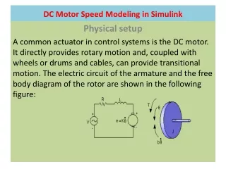
Brushless DC Motors • Standard DC motor – Magnetic field is stationary in stator, rotor poles switch polarity due to commutation to provide constant rotation. • Brushless DC motor – Magnetic field of rotor is fixed (imagine permanent magnet). Magnetic field in stator poles is electronically commutated, provides rotating magnetic field. Rotor follows… • Motor contains internal position encoder to provide position feedback to the control system. EMC_Brushless_and_Stepper_Motors Roger Enns
DC Brushless Motors cont’d • Advantages: • High efficiency (no losses across brushes) • Absence of arcing at brushes – reduces electrical noise. • High-speed operation possible • High reliability, low maintenance • Applications: • Robotics • Aerospace • Biomedical ( heart pump motors) EMC_Brushless_and_Stepper_Motors Roger Enns
DC Stepper Motors • Rotate in discrete steps. • Provide holding torque when stationary. • Allow accurate shaft positioning without shaft encoder. • Must be used with stepper motor controller. • Specified based on step increment: 18º, 15º, 7.5º, 5º, 1.8º are common. • If applied torque exceeds holding torque, rotor turns, falling “out of step”. EMC_Brushless_and_Stepper_Motors Roger Enns
Full-Step Stepper Operation EMC_Brushless_and_Stepper_Motors Roger Enns
Half-Stepper Operation EMC_Brushless_and_Stepper_Motors Roger Enns
Stepper Motor Operation • Steppers are used for accurate positioning: Robotics, printers, feeders, etc. • Stepper motors must be accelerated and decelerated at a controlled rate (‘ramping’) to prevent falling out of step • Continuous operation at uniform speed is known as ‘Slewing’. • Required Reading: Pages 1-30 LeesonMotors.pdf on scratch drive. EMC_Brushless_and_Stepper_Motors Roger Enns