Download
1 / 46
460 likes | 673 Views
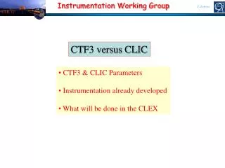
Instrumentation Working Group. CLIC 07. T. Lefevre. CTF3 versus CLIC. CTF3 & CLIC Parameters Instrumentation already developed What will be done in the CLEX. CLIC 07. 800 Klystrons low frequency high efficiency. Power stored in electron beam. 144000 Accelerating Structures

E N D
Instrumentation Working Group CLIC 07 T. Lefevre CTF3 versus CLIC • CTF3 & CLIC Parameters • Instrumentation already developed • What will be done in the CLEX
CLIC 07 800 Klystrons low frequency high efficiency Power stored in electron beam 144000 Accelerating Structures high frequency high gradient Power extracted from beam in resonant structures Electron beam manipulation Long RF Pulses P0 ,n0 ,t0 Short RF Pulses PA = P0 N1 tA = t0 / N2 nA = n0 N3 CLIC Drive Beam T. Lefevre What does the RF Power Source do ? The CLIC RF power source can be described as a “black box”, combining very long RF pulses, and transforming them in many short pulses, with higher power and with higher frequency
CLIC 07 Delay loop 2 gap creation, pulse compression & frequency multiplication Transverse RF Deflectors Combiner ring 3 pulse compression & frequency multiplication Combiner ring 4 pulse compression & frequency multiplication Drive Beam Decelerator Sector (24 in total) Power Extraction Drive beam time structure - final Drive beam time structure - initial 240 ns 240 ns 5.8ms 140mstotal length - 24 24 sub-pulses - 4.2 A 2.4 GeV - 60 cm between bunches 24 pulses – 100 A – 2.5 cm between bunches CLIC Drive Beam T. Lefevre Drive Beam Accelerator efficient acceleration in fully loaded linac RF Power Source Layout
CLIC 07 Covered by CTF3 * Covered by EUROTeV * Feasibility study done – need development by industry. N.B.: Drive beam acc. structure parameters can be adapted to other klystron power levels Motivation T. Lefevre The CLIC Technology-related key issues as pointed out by ILC-TRC 2003 R1: Feasibility • R1.1: Test of damped accelerating structure at design gradient and pulse length • R1.2: Validation of drive beam generation scheme with fully loaded linac operation • R1.3: Design and test of damped ON/OFF power extraction structure R2: Design finalization • R2.1: Developments of structures with hard-breaking materials (W, Mo…) • R2.2: Validation of stability and losses of DB decelerator; Design of machine protection system • R2.3: Test of relevant linac sub-unit with beam • R2.4: Validation of drive beam 40 MW, 937 MHz Multi-Beam Klystron with long RF pulse • R2.5: Effects of coherent synchrotron radiation in bunch compressors • R2.6: Design of an extraction line for 3 TeV c.m.
CLIC 07 Motivation T. Lefevre Motivation and goals of CTF3 collaboration • Build a small-scale version of the CLIC RF power source, in order to demonstrate: • full beam-loading accelerator operation • electron beam pulse compression and frequency multiplication using RF deflectors • Provide the RF power to test the CLIC accelerating structures and components • CTF3 is being built at CERN by a collaboration modeled on the large physics experiments • 23 institutes from 12 countries • Chairman of collaboration Board: M. Calvetti (INFN-LNF) • Spokesperson: G. Geschonke (CERN) Will be largest LC test facility constructed M. Huening, A. Mosnier, V. Shiltsev & T. Raubenheimer CLIC Advisory Committee Report
CLIC 07 Drive Beam Accelerator (2004) Delay Loop (2005) Drive Beam Injector (2003) CTF3 Evolution CLEX (2007-08) TL2 (end 2007) Combiner Ring (2006-07) 16 Institutes CTF3 Complex T. Lefevre CLIC Test Facility 3 to show the feasibility of the CLIC RF Source & Two Beam Acceleration for a multi-TeV e+-e- collider
CLIC 07 Initial time structure Final time structure 140 ns 140 ns 1.56 ms train length – 4A, 150MeV 20 cm between bunches 140ns pulse - 30A, 150MeV 2.5cm between bunches CTF3 Principle T. Lefevre Bunch frequency multiplication by a factor 8 : from 1.5 to 12GHz 42m Delay loop x2 (8-10ps bunch length) RF deflectors for injections in the rings Linac 2-4ps bunch length CLEX (1ps bunch length) 84m Combiner ring (x4) (8-10ps bunch length)
CLIC 07 CLIC Drive Beam / CTF3 T. Lefevre The thermal limit for ‘best’ material (C, Be, SiC) is ~ 1 106 nC/cm2 • Control of beam loss to prevent beam induced damage (10-4) • Use of non-intercepting / non degradable beam diagnostic • Strong scaling factor from CTF3 to CLIC
CLIC 07 Measurement @ CTF3 T. Lefevre What is presented in this talk
CLIC 07 Full beam-loading acceleration in TW sections No High current beam most of RF power (≥ 95%) to the beam High efficiency acceleration scheme T. Lefevre RF to load RF in No beam “short” structure - low Ohmic losses
CLIC 07 Gacc unloaded Transient DP/P (%) -5 0 5 Lstruct Steady state loaded Time resolved beam energy spectrum measurement in CTF3 s 100 200 300 400 Time (ns) Ebeam E0 E0 /2 steady state tfill t Time resolved spectrometry @ CTF3 T. Lefevre RF Power Source “building blocks” Full beam-loading acceleration in TW sections
CLIC 07 Time resolved spectrometry @ CTF3 T. Lefevre e- Bending Magnet Segmented Dump Or Slit Dump OTR Screen & Segmented PMT • 24 Tungsten plates (2mm thick) spaced by ~ 1mm • Connected to 50 Ω to the ground • Slit dump ( 2mm slit and a dump in steel) • 32 channels PMT (Hamamatsu) • 2mm spatial resolution • 36dB, 100MHz amplifier in the klystron gallery
CLIC 07 OTR & Segmented Photomultiplier T. Lefevre • Problem with synchrotron light in the bending magnet • @ 100MeV: ph/e- 4.10-3(SR) versus 9.10-3 (OTR) • Parabolic OTR screen in order to optimize the collection of the light Implement a carbon foil as SR light shielding
CLIC 07 Segmented Dump T. Lefevre Fluka simulations of energy deposition • Segmented DUMP • 32 Tungsten plates (2mm thick) spaced by ~ 1mm • Insulator in Alumina (rad-hard) • New Ceramic electronic card connected to the dump segments • Alignment balls has been added • Connected to 50Ω to ground (increasing signal to noise ratio) • 20MeV Electrons • Beam size in x : 3mm sigma Results electrons • Collimator in Steel • Mounted on the beam tube • 32 vertical slits 400microns thick • Water cooled
CLIC 07 OTR Light Camera OTR Screens T. Lefevre OTR screen Created when charged particles pass through the interface between two materials with different permittivity Electrons lenses Camera Angular distribution of OTR Quad Scan in X Quad Scan in Y
CLIC 07 High reflectivity screens for low charge beam • Thin Al foil is fragile • Using 200mm Si wafer with a very good surface quality • Adding an Aluminum coating to provide an excellent reflectivity coefficient (90%) Thermal resistant material for high charge beam • Non homogeneous surface of C • 200mm thick Polished CVD SiC 30% Reflectivity coefficient OTR Screens limitations T. Lefevre
CLIC 07 • 200fs time resolution at best using state of the art Cameras : FESCA 200 • Limitations : • (i) Initial velocity distribution of photoelectrons : narrow bandwidth optical filter • (ii) Spatial spread due to the size of the slit • (iii) Dispersion in the optics Bunch length monitoring T. Lefevre - Streak Camera - Use Synchrotron light produced in the rings or OTR/Cherenkov screens in a linac Focusing element ‘Streak cameras uses a time dependent deflecting electric field to convert time information in spatial information on an intensified CCD’ TUPB29, TUPC11, WEPB05, WEPB12, WEPB20
CLIC 07 OTR@ linac SR@ Delay Loop Sweep speed of 10ps/mm “Nominal” chicane - R56 = 0.45 s = 8.9ps (2.7 mm) s = 4.5ps (1.4 mm) Bunch length monitoring T. Lefevre ‘ CTF3 Complex’ Bunch length can be manipulated at the end of the linac using a magnetic chicane • 2 Optical lines to the streak camera • Synchrotron Radiation in the Delay Loop • OTR in the linac at the exit of the Delay Loop
CLIC 07 Deflecting Voltage RF deflector phase Betatron phase advance (cavity-profile monitor) Bunch length RF deflector wavelength Beam energy • Resolution will depend on : (sub-100fs) • Screen spatial resolution • Deflecting power • Beam optic between the deflector and screen Beta function at cavity and profile monitor Bunch length monitoring T. Lefevre Old (1960-70’s) idea to use RF deflector as a bunch length monitor • The RF Deflector can be seen as a relativistic streak tube. • The time varying deflecting field of the cavity transforms the time information into a spatial information • The bunch length is then deduced measuring the beam size at a downstream position using a screen (or Laser Wire Sanner) sy0 sy Deflecting mode TM11 MOO2A02, TUPB13, TUPB3 & WEO2A03 by A. Cianchi,
CLIC 07 OTR Light Camera Bunch length monitoring T. Lefevre 3GHz RF Deflector 30o offcrest on last klystron Bunch length 0.5 mm (1.2ps) Bunch length 2.5 mm (6ps)
CLIC 07 mm size bullet • Degradable profile monitor • ‘Kalachnikov’ : bullet scanner Beam loss detector e- • Neutral beam scanner : Gas jet C. Dimopoulou, PS/BD note 99-12 • Any new idea highly welcome… No conclusion T. Lefevre How can we make profile monitor for the Drive Beam Linac • No non-intercepting transverse profile monitor available for low energy electron beams in a linac
CLIC 07 T. Lefevre Back-up Slides
CLIC 07 P , n 0 0 2 P , 2 ´ ´ n 0 0 P , n 0 0 Deflecting Field Beam combination/separation by transverse RF deflectors RF Deflector T. Lefevre RF Power Source “building blocks” Transverse RF Deflector, n 0
CLIC 07 Beam combination/separation by transverse RF deflectors CLIC Drive Beam T. Lefevre RF Power Source “building blocks” P0 / 2 , n0 / 2 Transverse RF Deflector, n 0 P , n 0 0 P0 / 2 , n0 / 2 Deflecting Field
CLIC 07 Phase coding How to “code” the sub-pulses Sub-Harmonic Bunching n0 / 2 Combination scheme 180 phase switch Acceleration n0 Deflection n0 / 2 even buckets • Delay Loop odd buckets • RF deflector Delay Loop T. Lefevre Gap creation & first multiplication 2 Ldelay = nl0 = c Tsub-pulse
CLIC 07 1 8 666 ps 8.5 · 666 ps = 5.7 ns T. Lefevre Sub-harmonic bunching system Streak camera – 500 ps/mm Fast phase switch from SHB system (CTF3) satellite main 3 TW Sub-harmonic bunchers, each fed by a wide-band TWT
CLIC 07 2 2 1 3 3 1 Delay Loop @ CTF3 T. Lefevre Beam recombination in the Delay Loop (factor 2)
CTF3 bunch train combination CLIC 07 Sweep speed 250ps/mm OTR light after recombination SR light in the Delay Loop T. Lefevre Phase coding in the sub-harmonic bunching system Bunch frequency multiplication in delay loop
CLIC 07 injection line 1st turn 2nd septum 1st deflector 2nd deflector local inner orbits lo RF deflector field 4rd 3rd lo/4 T. Lefevre Frequency multiplication - Combiner Ring RF injection in combiner ring (factor 4 for simplicity) Cring = (n + ¼) l
CLIC 07 Tsub-pulse Dt = 2 Tsub-pulse N pulses pulse train from DL 4 1 turn 2 3 st nd rd th N/4 pulses Final pulse train T. Lefevre Frequency multiplication - Combiner Ring Cring = c Dt = c 2 Tsub-pulse
Combiner ring bunch manipulation CLIC 07 333 ps 83 ps T. Lefevre x Bunch combination (factor 4) 2003 CTF3 Preliminary Phase results t
CLIC 07 OTR light and sweep speed 100ps/mm Wiggler off Bunches from the DL Bunch from the linac Wiggler on Bunches from the DL later by 12ps (3.6mm) • Better RF combination • 7.5GHz • 9GHz 333 ps t (ns) Bunch train combination T. Lefevre ‘ Adjust the delay loop length with a magnetic wiggler’
Stretching in the Frascati Chicane CLIC 07 T. Lefevre
CLIC 07 Beam Position (mm) RF Phase (o) Use a Beam Position Monitor close to the Profile monitor to calibrate the deflection angle R34 = transfer Matrix element from cavity to the BPM Make a power scan at zero crossing and (zero crossing – 180o) to check if there is no perturbation from linac wakefields Bunch length monitoring T. Lefevre - Calibration of RF Deflector -
CLIC 07 RF deflector on : 0 Xing Bunch length monitoring T. Lefevre - Bunch Length Measurement with the 1.5GHz RF Deflector of the Delay Loop - OTR screen RF deflector off • Maximum power of 20MW • 5degrees @1.5GHz = 9.25ps (4mm) With this setting, the resolution is better than 1ps More tests must be done to check where the limits are snoRF = 0.35mm s0Xing = 2.9mm (6.7ps)
CLIC 07 Beam Position monitor T. Lefevre Inductive Pick-up @ CTF3 Inductive Pick-up @ CTF3 • Measure the beam image current on the beam pipe using 8 electrodes • Electrodes are combined in pairs so that each transformer sees half of the load • Frequency low cut-offs are limited by connection parasitic resistances and primary electrode inductance Design by Marek Gasior : CERN-AB-2003-063
CLIC 07 Beam Position monitor T. Lefevre Inductive Pick-up @ CTF3 • Resolution already DI/I = 10-3 • For CLIC Drive Beam (100ms pulse duration) need to lower the low frequency cut off
CLIC 07 Beam Position monitor T. Lefevre Inductive Pick-up @ CTF3 >15 BPMs already installed in CTF3
CLIC 07 High precision position measurement T. Lefevre Diagnostics Beam position L Soby – I. Podadera Test in CTF3 late this year
CLIC 07 WCM Manipulating high beam charge T. Lefevre Machine protection system @ CTF3 • Compare signals from consecutive Wall Current Monitors • If losses is detected, the electron gun is switched off • Time response dominated by cable length (>311ns) D. Belohrad, Dipac Conference, Lyon, p.255, (2005) P. Odier, CERN-AB-2003-069 For CLIC DB the system will have to rely on Beam Loss Monitors
CLIC 07 High Bandwidth Wall Current Monitor T. Lefevre L Soby – A. D‘Elia Diagnostics Wall Current Monitor
CLIC 07 Beam Phase monitor T. Lefevre Drive Beam Longitudinal stability • Use RF pick-up (30GHz) to measure the Drive Beam phase at 2 locations (≠ longitudinal dispersion) • Use tuners to correct the phase error • Controller • Single shot device • +/- 50MHz bandwidth (react fast) • 10fs resolution for phase measurement (0.1o @ 30GHz) • +/- 5degrees range • 6dB amplitude range Layout of Phase feedback • Possible candidates for Tuners • RF deflectors in a dispersive and anisochronous area • Accelerating structures and chicane
CLIC 07 Beam Phase monitor T. Lefevre Main/Drive Beam Phase stability 4% luminosity reductionsf= 0.225o Dz= 6 mm F. Stulle -PSI
CLIC 07 Beam Phase monitor T. Lefevre Femtosecond Phase detection • Mixing the 30GHz signal from the beam down to 750MHz • Measure the 750MHz signal Phase and Amplitude • Goal to find a phase detector@750MHz with noise below 0.03o • Phase detector can be multipliers or mixers By J. Sladen and A. Andersson
CLIC 07 Beam Phase monitor T. Lefevre Diagnostics Phase measurement J. Sladen, A. Andersson
CLIC 07 T. Lefevre CLic Experimental Areas (CLEX)