Download
1 / 27
280 likes | 449 Views
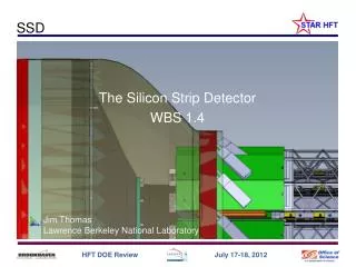
The Silicon Strip Detector an overview and introduction. Jim Thomas Lawrence Berkeley National Laboratory. SSD Location in STAR. IFC Inner Field Cage. OFC Outer Field Cage. Magnet End Cap. TPC Volume. SSD Surrounds the PXL & IST @ 22 cm radius. Solenoid.

E N D
The Silicon Strip Detectoran overview and introduction Jim Thomas Lawrence Berkeley National Laboratory
SSD Location in STAR IFC Inner Field Cage OFC Outer Field Cage Magnet End Cap TPC Volume SSD Surrounds the PXL & IST @ 22 cm radius Solenoid The SSD is an existing detector that needs an upgrade to meet HFT specs
~ 50 cm Si Detectors Inside the TPC SSD IST Beampipe • Goal: graded resolution and high efficiency from the outside in • TPC – SSD – IST – PXL • TPC pointing resolution at the SSD is ~ 1 mm • SSD pointing at the IST is ~ 400 mm = 0.98 • IST pointing at PXL 2 is ~ 400 mm = 0.98 • PXL 2 pointing at PXL1 is ~ 125 mm = 0.93 • PXL1 pointing at the VTX is ~ 40 mm = 0.94 Pixel Detector The challenge is to find tracks in a high density environment with highefficiency because a D0 needs single track 2
SSD Overview and a few acronyms Transition Cone (shroud removed) WSC Outer Support Cylinder (OSC) 44 cm 20 Ladders 4.2 Meters East Support Cylinder (ESC) ~ 1 Meter
SSD The Silicon Strip Detector The SSD is an existing detector
~ 50 cm SSD Parameters • Double sided Si wafers modules: 300 mm thick with 95 mm strips that are 4.2 cm long • 768 strips per side • Strips crossed at 35 mrad effective resolution 30 mm x 900 mmm • One layer at 22 cm radius • 20 ladders, 67 cm long • 16 modules per ladder • air cooled • < 1.2 • 1 % radiation length @ = 0
Status of the ladders • The last run with the SSD was in 2007 … it wasn’t a good run • cooling failures led to overheating and poor performance • perhaps related to this, there were several bias capacitors that failed on the modules. This caused 3 ladders to ‘trip’ frequently. • some ladder boards were damaged (ADC aging or other issues) • Status in May of 2008 • Six good ladders • Seven ladders with one bad hybrid (half module) • Nine ladders with several bad modules • bad ladder boards do not matter because we are going to replace them • The ladders were refurbished in 2008 (see next page) • Now 94% of modules (on 20 ladders) are good • The modules & ladders have not be used since these repairs • The ladders have not been operated since 2008
The SSD is an existing detector upgrade Existing Detector w/ Si modules Electronics Upgrade in progress Mechanical & Conv. systems … early days
Progress: Ladder 0 is ready to be surveyed Target on end of wafer (backside) Reference point for survey and mounting on OSC Targets on edges of wafer (front)
Readout Electronics – the heart of the upgrade Ladder cards – 1.4.2.1 RDO (1 of 8) – 1.4.2.2 Slave FPGA VME FPGA VME interface See talks by C. Renard and M.J. LeVine Fiber links Slave FPGA Slave FPGA Master FPGA DAQ interface DAQ – 1.4.2.3 DDL SlaveFPGA TRG interface SlaveFPGA South platform VME crate Outer support cylinder DAQ room
Progress: Ladder Card built and tested • Prototype with interposer card working since last summer • FPGAADC – DAC test as voltage ref. for ADC • A new layout has recently been completed and will be sent off for fabrication (see talk by C. Renard) • Milestone: Passing from prototype to pre-production version
Progress: ‘Quick’ RDO built and tested • Prototype RDO board w/services for 1 ladder • A complete RDO board has recently been completed and sent off for fabrication • Milestone: Passing from prototype to pre-production version
Progress: Readout Board Status (RDO) • ✓Design of Slave FPGA complete • ✓Pin outs for Master and VME FPGAs done • ✓Full RDO board has been designed and laid out • ✓ Components ordered • Fab will begin in July See talk by M.J. LeVine
Progress: Slow Controls and Conventional Systems • We have developed a slow controls interface to the new Power supplies (See talk by Weihua Yan) • Working on the more complex problem of JTAG communication to the ladders • Prototype quantities of PS and Power modules are in-house • Cooling system is in-house and has been tested. Cooling system – vacuum Instrumentation for cooling
Mechanical Engineering: the OSC & Shroud SSD Ladders go here
Progress: Mechanical Engineering • Cable trays will be installed around FGT planes • OSC with shroud and E&M shield installed • SSD Specific work not yet complete 10 cm
Project Requirements: CD-4 Deliverables • Instrument 20 of the existing SSD ladders with new readout electronics compatible with STAR TPC readout • SSD to be installed on the Outer Support Cylinder • Provide cabling and cooling compatible with the IDS structure and FGT
SSD CD4 Requirements on Dead time • Dead-time as a function of random trigger rate • Simulated performance with 3% occupancy • The SSD will have 4 buffers as part of the firmware • Multiple buffers hide the downstream DAQ from the dead-time of the system for randomly arriving triggers CD-4 requirement < 10% dead time at 500 Hz
Summary • The SSD upgrade project is moving ahead rapidly • We have a well developed prototype, test and fabrication plan • We are just starting the fabrication of our pre-production LB and RDO boards • The coming year will be dominated by fabrication of production electronics, mechanical engineering, software development and integrated testing. • Resources necessary for the completion of the project are in hand and, for the most part, readily available • The costs are under control. • Keeping to schedule will be a challenge; including testing the new electronics on one ladder, as well as integrated testing of the full system at STAR. • Our goal is to install the full SSD in time for Run 14 (2013-2014)
Backup Slides Backup Slides
Modifications Needed for the SSD Upgrade • Use existing SSD silicon sensors • Upgrade readout from 200 Hz to 1 kHz • Improve reliability of sub-systems
SSD WBS • 1.4.1 Mechanics • 1.4.2 Electronics • 1.4.2.1 Ladder Board • 1.4.2.2 RDO Board • 1.4.2.3 DAQ Board • 1.4.3 Detector Assembly • 1.4.3.1 Survey • 1.4.3.2 OSC Assembly • 1.4.4 Infrastructure • 1.4.4.1 Cables • 1.4.4.2 Power Supply • 1.4.4.3 Cooling • 1.4.4.4 Slow Controls • 1.4.4.5 FPGA Software The Work Breakdown Structure reflects the elements shown on the previous page
We kept the SSD, it is a beautiful detector! • The SSD is thin • 1% - double sided Si • The SSD lies at an ideal radius • 22 cm - midway between IP and IFC • The SSD has excellent resolution • (rumor says better than design) • Replacing the SSD was not an option • too expensive
Getting a Boost from the TPC OFC • The TPC provides good but not excellent resolution at the vertex • ~ 1 mm • The TPC provides an excellent angular constraint on the path of a predicted track segment • This is very powerful. It gives a parallel beam with the addition of MCS from the IFC • The best thing we can do is to put a pin-hole in front of the parallel beam track from the TPC • This is the purpose of the SSD and IST • The SSD and IST do not need extreme resolution. Instead, they maintain the parallel beam and don’t let it spread out • MCS limited • The PXL does the rest of the work TPC IFC MCS Cone VTX The Gift of the TPC