Download

1 / 20
220 likes | 624 Views
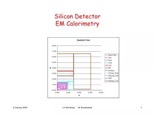
Detector Control System for the Silicon Pixel Detector. SSD (Silicon Strip Detector) SDD (Silicon Drift Detector) SPD (Silicon Pixel Detector). 2 layers splitted in 10 sectors each sector carries on 6 staves: 4 outer layer + 2 inner layer each stave splitted in 2 half-stave

E N D
Detector Control System for the Silicon Pixel Detector SSD (Silicon Strip Detector) SDD (Silicon Drift Detector) SPD (Silicon Pixel Detector) ALICE DCS Workshop 28/29 May 2001 Vito Manzari, INFN Bari
2 layers splitted in 10 sectors • each sector carries on 6 staves: • 4 outer layer + 2 inner layer • each stave splitted in 2 half-stave • half-stave basic module ALICE DCS Workshop 28/29 May 2001 Vito Manzari, INFN Bari
ALICE DCS Workshop 28/29 May 2001 Vito Manzari, INFN Bari
SPD Basic Building Blocks 1 data and 2 control links (~200m) Half stave ~193 mm Ladder 2: 70.72 mm Ladder 1: 70.72 mm 16.8 mm 32 columns Pixel detector Power supply ~1m PCMCM Frontend chip Carrier bus 256 rows 15.86 mm Pixel Cell 50 m 425 m ALICE DCS Workshop 28/29 May 2001 Vito Manzari, INFN Bari
Electronics System Block Diagram ALICE DCS Workshop 28/29 May 2001 Vito Manzari, INFN Bari
Services • Cooling • LV power requirements • LV currents each half stave (@ V ≈ 1.6V nominal) • I analog ≈ 4A, I digital ≈ 3A • Conductor (Cu) • width: 2 mm strip on kapton, thickness ≈ 0.20mm ≈ 1.4% X0 • resistance ≈ 40 mOhm • Regulation and filtering of power supplies (space/cooling constraints !) • rad-hard linear regulator chip (P. Jarron) at patch-panels • filtering with passive components on bus • Fibre-optic links • 3 (possibly 4) fibres each half-stave • single fibre diameter (tight jacket) ≈ 0.9mm, fibre ribbon pitch = 0.25mm ALICE DCS Workshop 28/29 May 2001 Vito Manzari, INFN Bari
Overview of voltage and current requirements per half-stave • Base unit: 1 half-stave = 10 pixel chips • SPD (Silicon Pixel Detector) => 120 half-staves • Separate analog, digital, detector bias, MCM power supplies • Necessary channels: • - 120 analog power + ground + sense wires • - 120 digital power + ground + sense wires • - 120 detector bias + ground • - 120 MCM power + ground + sense wires ALICE DCS Workshop 28/29 May 2001 Vito Manzari, INFN Bari
Possible solutions • All power supplies outside the pit distance from detectors => 200 m • Power supplies for analog electronics inside the pit distance from detectors => 40 - 50 m Power supplies for digital electronics and detector bias outside the pit distance from detectors => 200 m • All power supplies inside the pit distance from detectors => 40 - 50 m ALICE DCS Workshop 28/29 May 2001 Vito Manzari, INFN Bari
ALICE Experiment ALICE DCS Workshop 28/29 May 2001 Vito Manzari, INFN Bari
The NA57 slow control system (CAEN SY527) ALICE DCS Workshop 28/29 May 2001 Vito Manzari, INFN Bari
All power supplies outside the pit(distance from detector => 200 m) - easy to replace the damaged board during the run (not on-board spare channels) - no radiation and magnetic field problems - increased length and cross section of the analog power cables - voltage drop on the analog power cable analog power digital power detector bias CAEN SY1527 (for all power supplies) outside the pit 200 m SPD Shoebox with capacitive filter 4 - 5 m ALICE DCS Workshop 28/29 May 2001 Vito Manzari, INFN Bari
Analog power supplies inside the pit (distance from detector => 40–50 m); digital and detector bias power supplies outside the pit (distance from detector => 200 m) - spare analog channels => necessary rele’ system - no digital and bias spares CAEN SY1527 (digital power and detector bias) outside the pit 200 m Shoebox with capacitive filter and control logic SPD CAEN SY1527 (analog power) inside the pit 4 - 5 m 40 m ALICE DCS Workshop 28/29 May 2001 Vito Manzari, INFN Bari
Several cables under test • Line impedance adjust: solution under study from CAEN to make use of sense wires or line impedence adjustment 40-50 m PIXEL 40-50 m ALICE DCS Workshop 28/29 May 2001 Vito Manzari, INFN Bari
Cost estimate 1st solution (all PS outside) • 3 CAEN SY1527 mainframe + 9 A1532 (optional P.S.) 60 KChF • 18 + 1 programmable board A1517B (5V/3.6A, 14 ch) 137 KChF • 5 + 1 programmable board A1519B (250V/1mA, 28 ch) 48 KChF • Cable for digital power (10.5 ChF/m) 42 KChF • Cable for detector bias (5.53 ChF/m) 11 KChF • Cable for analog power (10.5 ChF/m) 63 KChF TOTAL 360 KChF 2nd solution (analog PS inside and digital PS outside) • 4 CAEN SY1527 + 12 A1532 80 KChF • 19 + 3 programmable board A1517B (5V/3.6A, 14 ch) 159 KChF • 4 + 1 programmable board A1519B (250V/1mA, 28 ch) 48 KChF • Cable for digital power (10.5 ChF/m) 42 KChF • Cable for detector bias (5.53 ChF/m) 11 KChF • Cable for analog power (10.5 ChF/m) 10.5 KChF TOTAL 350.5 KChF ALICE DCS Workshop 28/29 May 2001 Vito Manzari, INFN Bari
Test System available in Bari Lab: CAEN mainframe SY1527 A1734N board (12 channels, 250 to 6KV, 7mA to 100 mA) Ethernet “TCP/IP” CAEN OPC server installed on pcal04 OPC client via TCP/IP => under study (first tests performed with an OPC client from National Instruments installed on pcal01) Test System for CAEN SY1527 ALICE DCS Workshop 28/29 May 2001 Vito Manzari, INFN Bari
Example of remote monitoring This OPC client from National Instruments runs on a remote workstation (pcal01) ALICE DCS Workshop 28/29 May 2001 Vito Manzari, INFN Bari
All power supplies inside the pit (distance from detector => 40-50 m) • - reduction cost and length of the conventional analog power cables • - reduced voltage drop on the analog power cable • - no access during the run • - impossible to replace damaged board, necessary spare channels for the • analog-digital power supplies and detector bias => notable cost increase • Alternative solution ---> Adoption of Voltage Regulators with standard • powerful power supply • Power Supply: ELIND 30KL 38/80 autoranging (0-30 V, 0-80 A) • Voltage regulator: L4913 (P. Jarron), others ALICE DCS Workshop 28/29 May 2001 Vito Manzari, INFN Bari
Solution based on Voltage Regulators ALICE DCS Workshop 28/29 May 2001 Vito Manzari, INFN Bari
Main parameters of the DCS for the ITS Pixel (1) ALICE DCS Workshop 28/29 May 2001 Vito Manzari, INFN Bari
Main parameters of the DCS for the ITS Pixel (2) N.B. All analog channels ALICE DCS Workshop 28/29 May 2001 Vito Manzari, INFN Bari