Download
1 / 21
210 likes | 226 Views
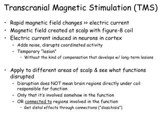
This project aims to develop a high current pulse generator for the application of transcranial magnetic stimulation. It involves designing and testing various circuits and components to meet the functional and non-functional requirements of the machine. The goal is to create a user-friendly and cost-effective generator that can deliver accurate and controlled pulses in accordance with medical standards.

E N D
High Current Pulse Generator for the Application of Transcranial Magnetic Stimulation SDDEC04 Advisor: Professor Mani Mina Clients: Priyam Rastogi, Jayaprakash Selvaraj, Neelam Prabhu-Gaunkar Team Members; Curtis Richards, Yan Wang Brian Krkpatrick, Tania Alvarado, Abdul Bahashwan, Jonathan Rothfus
Sub-Teams • Power Circuit: • Curtis Richards, Tania Alvarado, Abdul Bahashwan • Rectification Circuit: • Yan Wang, Brian Kirkpatrick, Abdul Bahashwan • Micro-Controller Team: • Jonathon Rothfus, Brian Kirkpatrick • Chassis Team: • Tania Albarado, Yan Wang, Curtis Richards SDDEC04
Block Diagram of Circuit Wall Outlet/ Input Rectification Circuit Power Circuit Output/ Coils SDDEC04 Micro-Controller
Functional Requirements • Peak Current 2000 Amperes Sustained for 400 Microseconds • Rise or Fall Time of 100 Microseconds • Machine Powered by a 120Vrms Wall Outlet • 10 Pulses a Minute • Graphical User Interface (G.U.I) • Machine can Accept a Wide Range of Inductive Coil Designs SDDEC04
Non-Functional Requirements • Multiple Rectifiers are Available for Backup in the Event of Damage • User Friendly G.U.I. • Heavy Duty Chassis • Built in Analog Voltmeter • Fans to Increase Circuit Cooling • Less Expensive than Similar Generators on the Market SDDEC04
Market Survey and Cost Analysis • Cost Calculations Include Components and Labor Overhead • Benchmarked Machine is Based off of Devices Currently used for Lab Testing • Estimated Cost Reduction of 90% per unit SDDEC04
Micro-Controller • Essential Functionality • Relay Control • IGBT Control • Desired Functionality • Switch Waveform Types • Switch Current Levels • Monitor IGBT Temperature SDDEC04
Micro-Controller System Diagram SDDEC04
G.U.I. Concept SDDEC04
Power Circuit SDDEC04
Rectification Circuit SDDEC04
Technical Challenges • The Secondary and Primary Coils of the Transformer were Electrostatically Isolated • Mounting of Capacitors • Resistor Size SDDEC04
Operational Testing Overview • Test to Ensure Everything was Working as Designed • No Unforeseen Issues with Components SDDEC04
Capacitor Testing • Successfully Charged the Capacitor through the Rectification Circuit to 240 V • Accurately Measured the Voltage of the Capacitor with an Analog Voltmeter and Digital Multimeter • Charging Time is Approximately 10 seconds SDDEC04
Rectification Testing • Each of Our Rectification Circuits have been Tested without any Faults • Tested Individually Using Function Generator, Oscilloscope, and Voltmeter SDDEC04
IGBT Testing • Sent a Square Wave into the Gate with a D.C. Source as Input and Recorded the Output with the use of an Oscilloscope SDDEC04
Output SDDEC04
Project Milestones & Schedule • Circuit Design • Completed Week 8 • Components and Budget • Approved Week 9 • Components Received • Week 11 • Circuit Wiring • Completed Week 14 • Operational Testing • Completed Week 15 SDDEC04
Fall Schedule SDDEC04
Questions SDDEC04
Project Name: High Current Pulse Generator for the use of Transcranial Magnetic Stimulation. Start Date: January, 14 2018 End Date: Dec 12, 2018 24, 2017 Executive Summary Block Diagram: Functional Requirements: • Peak Current 2000 Amperes Sustained for 400 Microseconds • Rise or Fall Time of 100 Microseconds • Machine Powered by a 120Vrms Wall Outlet • 10 Pulses a Minute • Graphical User Interface (G.U.I) • Machine can Accept a Wide Range of Inductive Coil Design Define: Rectification Circuit Wall Outlet Power Circuit Output/ Coils Micro-Controller Non-Functional Requirements: • Multiple Rectifiers are Available for Backup in the Event of Damage • User Friendly G.U.I. • Heavy Duty Chassis • Built in Analog Voltmeter • Fans to Increase Circuit Cooling • Less Expensive than Similar Generators on the Market Output: SDDEC04 Next Semester; Team Members:Advisor: Professor Mani Mina Clients: Priyam Rastogi, Jayaprakash Selvaraj, Neelam Prabhu-Gaunkar Team: Curtis Richards, Yan Wang, Brian Kirkpatrick, Tania Alvarado, Abdul Bahashwan, Jonathan Rothfus Integrate Controlling Circuit Build and Test Biphasic Machine SDDEC04