Download
1 / 41
410 likes | 483 Views
Learn about the basic circuit diagram and operation stages of a clock pulse generator for physics, with emphasis on voltages and charging cycles.

E N D
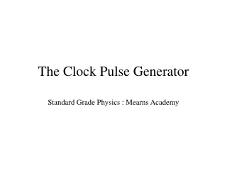
The Clock Pulse Generator Standard Grade Physics : Mearns Academy
The Clock Pulse Generator +6V R2 Y R1 A X C 0V This is the basic circuit diagram for the clock pulse generator.
The Clock Pulse Generator High = 1= +6V Low = 0 = 0V
The Clock Pulse Generator-in stages Y R1 A X C 0V At the start the capacitor is uncharged so the voltage at X is 0V. The NOT gate inverts the signal, so the voltage at A is 6V. The voltage at Y is also 6V.
The Clock Pulse Generator-in stages 6V R1 6V 0V C 0V At the start the capacitor is uncharged so the voltage at X is 0V. The NOT gate inverts the signal, so the voltage at A is 6V. The voltage at Y is also 6V.
The Clock Pulse Generator-in stages 6V High voltage R1 6V 0V C 0V Output is high.
The Clock Pulse Generator-in stages Y = 6V R1 A = 6V X = 0V C 0V The capacitor starts to charge up through the resistor R1
The Clock Pulse Generator-in stages Y = 6V R1 A = 6V X = 0V C 0V The capacitor starts to charge up through the resistor R1 The voltage at X will now become 6V The voltage at A will now become 0V The voltage at B will now become 0V
The Clock Pulse Generator-in stages Y = 0V R1 A = 0V X = 6V C 0V The capacitor starts to charge up through the resistor R1 The voltage at X will now become 6V The voltage at A will now become 0V The voltage at B will now become 0V
The Clock Pulse Generator-in stages Y = 0V High voltage R1 Low voltage A = 0V X = 6V C 0V Output is low
The Clock Pulse Generator-in stages Y = 0V R1 A = 0V X = 6V C 0V Since the voltage at X is now 6V and at Y it is now 0V, the capacitor will start to discharge through resistor R1
The Clock Pulse Generator-in stages Y = 6V R1 A = 6V X = 0V C 0V Since the voltage at X is now 6V and at Y it is now 0V, the capacitor will start to discharge through resistor R1 The voltage at X will now become 0V The voltage at A will now become 6V The voltage at B will now become 6V
The Clock Pulse Generator-in stages Y = 6V High High R1 A = 6V X = 0V C Low 0V …and the cycle repeats itself.
The Clock Pulse Generator-seeing the pulses +6V +6V Y=6V R1 A=6V X=0V C 0V When the capacitor is uncharged, the output of the NOT gate is high. There is no voltage difference across the LED so it does not light
The Clock Pulse Generator-seeing the pulses +6V +6V Y=0V R1 A=0V X=6V C 0V When the capacitor is charged, the output of the NOT gate is low. The voltage difference across the LED is 6V so it lights.
The Clock Pulse Generator Output High (LED Off) Output Low (LED On) Large R and C Low Frequency Small R and C High Frequency
The Clock Pulse Generator-the LED bit +6V +6V Y=0V R2 R1 A=0V X=6V C 0V The maximum voltage across the LED part of the circuit is 6V Why is there a series resistor R2 in this part of the circuit?
The Clock Pulse Generator-the LED bit +6V +6V Y=0V R2 R1 A=0V X=6V C 0V The maximum voltage across the LED part of the circuit is 6V The LED is protected by the resistor R2 because it will be damaged if it has more than 2V or 10mA.
The Clock Pulse Generator-the LED bit +6V +6V Y=0V R2 R1 A=0V X=6V C 0V Calculate the value of series resistor R2 Voltage across R2 = 4V, I = 0.01A, R = V/I = 4/0.01 =400Ω
The Clock Pulse Generator-the LED bit +6V +6V R2 =400Ω Y=0V R1 A=0V X=6V C 0V Calculate the value of series resistor R2 Voltage across R2 = 4V, I = 0.01A, R = V/I = 4/0.01 =400Ω
7-segment Display Page 23 in Notebook: The 7-segment display is named because it is made up of 7 separate LEDs, which light depending on which decimal number is required. Complete note on Page 23.
7-segment Display Zero …..a,b,c,d,e,f…..
7-segment Display Zero …..a,b,c,d,e,f…..
7-segment Display One ….. b,c…..
7-segment Display Two …..a,b,d,e,g…..
7-segment Display Three …..a,b,c,d,g…..
7-segment Display Four ….. b,c,f,g…..
7-segment Display Five ….. a,c,d,f,g…..
7-segment Display Six ….. a,c,d,e,f,g…..
7-segment Display Seven ….. a,b,c, …..
7-segment Display Eight ….. a,b,c,d,e,f,g …..
7-segment Display Nine ….. a,b,c,d,f,g …..
7 Segment Display Which number? 2
Putting it all together Binary Counter 7-segment Display Clock Pulse Generator
Putting it all together Binary Counter 7-segment Display Clock Pulse Generator Digital output
Putting it all together Binary Counter 7-segment Display Clock Pulse Generator 000101 Digital output Binary output
Putting it all together Binary Counter 7-segment Display Clock Pulse Generator 000101 5 Digital output Binary output Decimal output