Download
1 / 20
200 likes | 357 Views
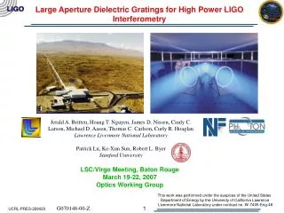
Large Aperture Dielectric Gratings for High Power LIGO Interferometry. Jerald A. Britten, Hoang T. Nguyen, James D. Nissen, Cindy C. Larson, Michael D. Aasen, Thomas C. Carlson, Curly R. Hoaglan

E N D
Large Aperture Dielectric Gratings for High Power LIGO Interferometry Jerald A. Britten, Hoang T. Nguyen, James D. Nissen, Cindy C. Larson, Michael D. Aasen, Thomas C. Carlson, Curly R. Hoaglan Lawrence Livermore National LaboratoryPatrick Lu, Ke-Xun Sun, Robert L. Byer Stanford University LSC/Virgo Meeting, Baton Rouge March 19-22, 2007 Optics Working Group This work was performed under the auspices of the United States Department of Energy by the University of California Lawrence Livermore National Laboratory under contract no. W-7405-Eng-48 G070148-00-Z UCRL-PRES-229023
Motivation • LIGO needs reflective grating beamsplitters for high-power interferometry. • Transmissive optics suffer from thermal lensing. • CO2 heating laser already required for ITM’s on initial LIGO. • Advanced LIGO will require 830kW of circulating power in the arms. For a 6cm spot size, that comes out to 30kW/cm2 of intensity. • Significant investment and progress has been made in the development of multilayer dielectric diffraction gratings for high-energy Petawatt-class laser systems. • Projects such as LIGO are poised to take advantage of this capability.
Laser Heating in Advanced LIGO End test mass Intracavity Power Level 830 kW Laser Power after Mode Cleaner 125 W Thermal lensing due to dn/dT Power recycling mirror Input test mass Laser 2.1 kW @Beam Splitter Mode Cleaner Signal recycling mirror (7%)
All Reflective Grating Reduces Bulk Heating • Gratings used as beamsplitter and input couplers to arm cavities. • No thermorefractive aberrations. Thermoelastic aberrations only. • No bulk absorption. Surface absorption only. • Greater design flexibility: allows the use of nontransparent substrates, which can be more thermally conductive. Intracavity Power Level 830 kW Littrow mounting. -1 overlaps with input 2.1 kW @Beam Splitter Laser Power after Mode Cleaner 125 W Input grating. Large aperture. ~80cm aperture required based on 67o Littrow spread. K.X. Sun, et. al, “All-reflective Michelson, Sagnac, and Fabry-Perot interferometers based on grating beam splitters,” Optics Letters, 8(23), p. 567-9 (1998)
Current Subject of Investigation Advanced LIGO Arm Cavity Diffraction efficiency > 99.5% Light incident on grating at Littrow angle (67o) Littrow mounting causes -1 diffracted order to circulate in cavity. Cavity finesse ~ 1200 830kW circulating power HR End Mirror The goal of this study is to build and test a working model of this configuration.
LIGO’s Requirements for Gratings 1 P. Barriga, et. al, “Numerical calculations of diffraction losses in advanced interferometric gravitational wave detectors,” http://www.ligo.org/pdf_public/barriga.pdf 2 C. Zhao, et. al, “Compensation of Strong Thermal Lensing in High Optical Power Cavities,” gr-qc/0602096 v2 3 Miyakawa, et. al, “Measurement of Optical Response of a Detuned Resonant Sideband Extraction Interferometer,” LIGO-P060007-00-R
substrate substrate substrate substrate MLD grating fabrication process flow resist layer substrate Transfer- etch (RIBE) Cleaning & Metrology Design (efficiency, E-field distribution, …) Multilayer oxide deposition Clean Prime Resist coat Expose Develop Metrology 575 nm period (only part of process not done at LLNL) During manufacture, optics are exposed to heat, aggressive liquids, and vacuum processing.
In the past 18 months LLNL has produced 77 production gratings @ 1740 l/mm Apertures from 140 mm to 800 mm Over 11 m2 of grating surface with average efficiency > 96% LIGO project For use wavelengths from 1017 nm to 1064 nm
Ratioing scanning photometry setup @ LLNL for efficiency measurements Grating and HR on XZ translation stage • Ratio HR to beam in air at • beginning and end of test for absolute scale • Ratio grating to HR at same location for every • pass while scanning grating over beam Signal detector Fused silica window Reference detector 500 mW CW 1064 nm laser Fused silica wedge
0.90 0.92 0.94 0.96 0.98 1.00 >99% diffraction efficiency gratings have been delivered to Stanford 1740 line/mm HfO2/SiO2 grating on BK7 substrates #011 (200x100 mm): 99.2% Ave, 0.3% RMS #021 (170x100 mm): 99.3% Ave, 0.2% RMS histogram of 10K data points histogram of 10K data points Design spec of >99.5% is achievable
Gratings exhibit flat diffracted wavefront Diffracted Wavefront at Littrow angle for 1053 nm (66.4o) 011 CW 021 CW Resolution 991 x 1005 Wedge 1.000 PV 0.1765 wv PVq(99%) 0.1509 wv RMS 0.0292 wv Strehl 0.967 Resolution 991 x 1005 Wedge 1.000 PV 0.1310 wv PVq 0.0837 wv RMS 0.0175 wv Strehl 0.988 CW orientation w/ S/N up
0.90 0.92 0.94 0.96 0.98 1.00 LIGO aperture required has been demonstrated for other projects #005 (800x400 mm) @ 1053 nm, 72.5o: 97.3% Ave, 0.7% RMS LLNL has delivered 13 production gratings at this size (800x400 mm) GSI5_06_04_19_221034_EFF_XLS #011: 97.1% Ave @ 1053 nm, 72.5o:, so this grating could be >99% for LIGO conditions
Byer Group Laser Lab NPRO Oscillator and Rod Amplifiers 100~200 W Amplifiers Laser lab is being set up for high power cw laser heating characterization of LLNL gratings
He-Ne Laser Shack-Hartman Wavefront Sensor 4x Beam Expander MLD Grating Initial thermal testing of 100 mm diameter LLNL MLD witness grating LIGO 8 W NPRO oscillator with 2 stage 4 passes rod amplifier Mini Slab Power Amplifiers (300 W diode pump) Modecleaner 30W Single Frequency TEM00 1064nm laser Max power was 34.5 W in a 1.5mm spot: ~2 kW/cm2
Grating wavefronts measured at two power densities show no difference removed Tip, Tilt, and Piston 34.5 W, ~2 kW/cm2 11 W, 0.6 kW/cm2 PV: 53.4 nm, Rms: 9.4 nm PV: 59.3 nm, Rms: 11.2 nm 3mm HeNe Probe Beam
Next Steps • Fiber laser and amplifiers to enable 100 W of single mode light • Cavity configuration to enable thermal tests to reach ~30 kW/cm2 for centimeter-scale beams • Large-aperture efficiency measurements will be made at Stanford to corroborate LLNL measurements • Scatterometer measurements, including back leaks
Efficiency/Finesse Measurements planned for near future Single Frequency 6 W YAG laser 1064 nm wavelength Cavity end-mirror with piezo EO Modulator Circulator Intracavity Power ~1200 W LLNL Dielectric Grating on Translation Stage Servo Electronics
Thermal aberration measurement at higher power planned for near future Single Frequency 100 W YAG laser 1064 nm wavelength Or Fiber Laser 100 W Shack-Hartman Wavefront Sensor He-Ne Laser Beam Expander Interferometric Sensor CCD EO Modulator Circulator Intracavity Power ~20 kW Power Density > 30 kW/cm2 LLNL Dielectric Grating on Translation Stage Servo Electronics
Conclusions • Capability exists to manufacture large-aperture multilayer dielectric diffraction gratings for demanding LIGO applications • >99% diffraction efficiency in Littrow mount • kW power-handling capability • 80+ cm apertures