Download
1 / 20
380 likes | 1.57k Views
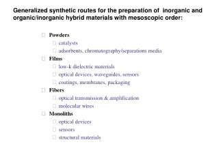
Processing of High k Dielectric Materials. Review by : Vivek Krishnan Materials Research and Education Center Auburn University, AL. Presentation Outline. Introduction – high and low k dielectric materials Applications Nucleation and growth Substrate choice Applications Conclusions.

E N D
Processing of High k Dielectric Materials Review by: Vivek Krishnan Materials Research and Education Center Auburn University, AL
Presentation Outline • Introduction – high and low k dielectric materials • Applications • Nucleation and growth • Substrate choice • Applications • Conclusions
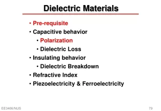
High and Low k Dielectrics • Integrated circuits • Silicon based dielectrics (SiO2, Si3N4, SiOxNy) • High k, greater than SiN (k>7) • Low k, lower than SiO2 (k<3.9) • Minimum value of k =1, air • Highest value, k = 24700, relaxor ferroelectric • Microelectronics, optoelectronics and cryoelectronics R. Singh and R.K. Ulrich, The Electrochemical Society, Interface, 1999
Questions • Why is atomic hydrogen important for growth of diamond thin films by CVD? • What is Bias Enhanced Nucleation?
Low k dielectrics • High circuit density and low power systems. • Interlevel dielectrics • Dielectric isolation between layers • Isolation within an individual layer of conducting lines • Current materials not able to withstand high processing temperatures. http://www.chm.bris.ac.uk/pt/diamond/end.htm
Memory devices • Use presence or absence of charge in a capacitor to represent “1” or “0”. • DRAM cell • One capacitor and one transistor • Cell stack contain a dielectric (SiO2 or SiN) between two electrodes (polySi) • 64 million transistors and capacitors in 1 cm2. Area Min. feature size (microns) http://www.chm.bris.ac.uk/pt/diamond/end.htm
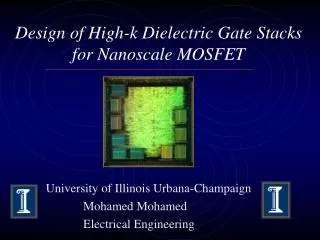
High k Dielectrics • MOS performance – thickness of gate dielectric material important • For oxides < 2nm, significant tunneling. • High k dielectric materials proposed. http://invsee.asu.edu/nmodules/Carbonmod/bonding.html
Need for High k dielectrics • High capacitance density • Higher surface area within same lateral area • Roughen bottom electrode – grow larger grains • Common approach - use thinner layers of SiO2 and SiN dielectrics • Problems – leakage current and dielectric breakdown • Use of high k dielectrics • Provide sufficient charge storage keeping thickness robust
Possess high k (k=25) CVD process commonly used. LPCVD using Ta (OC2H5)2 and oxygen gas mixtures Unfavorable leakage current characteristics. Improved by annealing with dry oxygen at high temperatures Eliminate organic inclusions in as-deposited CVD film. Can cause oxidation of polySi through diffusion of oxygen through the CVD film. Oxygen plasma annealing can improve processing. Tantalum Oxide Dielectrics
Process • Phosphorus-doped polySi deposited and patterned on substrates. • Tantalum oxide films deposited at 400C by LPCVD using Ta (OC2H5)2 and oxygen gas mixtures. • Ta (OC2H5)2 source vaporized at 170C and introduced using argon carrier. Thickness 10 nm • Oxygen plasma annealing carried out for 10 min at 100-400C using glow discharge generated at 0.5W/cm2 using 50kHz RF generator. • Oxygen plasma annealing pressure 1.5 torr. http://www.nyu.edu/pages/mathmol/modules/carbon/carbon1.html
Effect of temperature on thickness • Thickness of tantalum oxide films about 10 nm and independent of annealing temperature. • Only tantalum oxide films are oxidized on annealing. F.P. Bundy, The P,T Phase and Reaction diagram for elemental Carbon, 1979; J. Geophys. Res.85 (B12) (1980) 6930
Leakage Characteristics • Leakage currents measured by dc step method – 0.1V ramp intervals for capacitor area 4mm2. • Characteristics superior for plasma annealed films over dry oxygen annealed films. • Leakage characteristics for plasma annealed films improve with increased substrate temperature. • Reduction of impurities like carbon and hydrogen at higher temperatures. http://www.chm.bris.ac.uk/pt/diamond/end.htm
Film Characterization • EXAFS results • x- axis – distance of oxygen atoms from Ta atoms. • y –axis – magnitude of Fourier transform of EXAFS oscillations on xray absorption spectrum. • Plasma annealing can efficiently fill up vacancies. “Thin Film Diamond Growth Mechanisms”, James E. Butler and Richard L. Woodin, Thin Film Diamond, Ed. Lettington and Steeds, Pub. Chapman and Hill, 1994
Atomic Layer CVD • Surface controlled layer-by-layer process for the deposition of thin films with atomic layer accuracy. • Proceeds one atomic layer at a time through the alternative pulsing of precursors. • Each atomic layer formed in the sequential process is a result of saturated surface controlled reactions. • The surface control achieved with ALCVD allows single or tailored multiple layer deposition of thin, uniform and pinhole-free films over large areas. • Nanolaminates - stacked layers of different materials and other types of material mixtures with different material compositions can also be produced. http://www.asm.com/proc_alcvd.asp
Atomic Layer Chemical Vapor Deposition http://www.asm.com/proc_alcvd.asp
CVD technology for high-quality, ultra-thin films Inherently perfect step coverage, uniformity and reproducibility High-k dielectrics, Al2O3, ZrO2, HfO2 and their mixtures Lowest leakage currents when applied as a gate dielectric ALCVD Advantages . http://www.asm.com/proc_alcvd.asp
Problems and Current Trends • Commonly used high k dielectric materials not thermally stable on Si. • Some metal oxides are more stable but these have lower dielectric constants. • Bandgap inversely proportional to dielectric constant. • Thickness and barrier height exponentially affect leakage current and these have to be optimized. • Integration with complicated CMOS process. D.A. Buchanan, IBM J Res. Develop. Vol. 43 No.3 May 1999.
Conclusions • High k dielectric materials will help develop next generation microelectronic devices. • Newer materials and fabrication techniques need to be developed. • ALCVD and plasma annealing after CVD offer two ways to deposit ultrathin dielectric films.