Download
1 / 18
190 likes | 364 Views
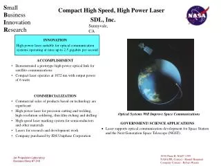
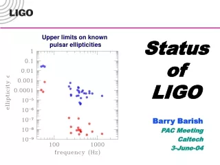
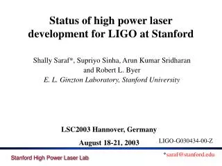
Status of high power laser development for LIGO at Stanford. Shally Saraf*, Supriyo Sinha, Arun Kumar Sridharan and Robert L. Byer E. L. Ginzton Laboratory, Stanford University. LSC2003 Hannover, Germany August 18-21, 2003. LIGO-G030434-00-Z. * saraf@stanford.edu. Outline.

E N D
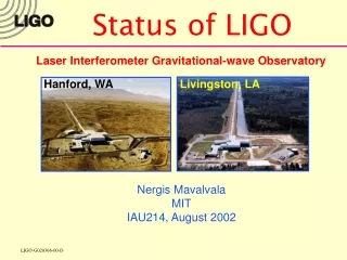
Status of high power laser development for LIGO at Stanford Shally Saraf*, Supriyo Sinha, Arun Kumar Sridharan and Robert L. Byer E. L. Ginzton Laboratory, Stanford University LSC2003 Hannover, Germany August 18-21, 2003 LIGO-G030434-00-Z *saraf@stanford.edu
Outline • Stanford approach to power scaling. • Experimental setup. • 100W demonstration results. • Scaling to 200W. • Future work.
MOPA vs OSCILLATOR • Rugged • Scalable • Single frequency • Power available despite element failure. • Less efficient. POWER-AMP PRE-AMP PRE-AMP PRE-AMP MOPA LOW POWER, ULTRA STABLE MASTER OSCILLATOR • Difficult to control • Single frequency operation involves injection locking. • Element failure usually means zero power. • More efficient. OSCILLATOR
10W LIGO MOPA System 20 W Amplifier ISOLATOR Lightwave electronics Experimental setup presented at LSC Livingston Mode-matching optics Ppump = 180 W edge pumped slab Ppump = 430 W P M C end pumped slab PM TEM00 power OC
End pumped slab geometry* • Motivation -> Higher efficiency • Near total absorption of pump light. • Confinement of pump radiation leads to better mode overlap 808nm Pump undoped end signal OUT 3.33 cm 1.5 cm 1.5 cm 0.6% Nd:YAG signal IN undoped end *Similar to TRW Hagop Injeyan, et. al. 808nm Pump 1.1 mm X 0.9 mm
Results of MOPA experiment • Single Pass Power output ~ 65 W (M2 < 1.1) • Depolarization ~ 1.5%. • P-P intensity fluctuations ~ 7% COLD SLAB OUTPUT 30 W PUMPED SLAB OUTPUT 65 W
Mode content of 65 W beam FSR of PMC TEM00 *** 74 % mode content in TEM00 *** P-P intensity fluctuations ~ 2% after PMC
Double pass setup for MOPA experiment *** 104 W demonstrated at M2 < 1.2 ***
Slab Issues for scaling to 200W Question: Why is the small signal gain of the end pumped slab much lower than expected? Answer: 30 - 35% pump scattered in undoped region. 808nm Pump TIR surfaces (top & bottom) Pump light leakage. 808nm Pump Rough surfaces (left & right)
Solutions towards improved pump confinement UD TIR surfaces (top & bottom) D POLISH UD ROUGHEN POLISH 1. POLISH UNDOPED SIDES AND ROUGH UP THE DOPED REGION. coating damaged ++ Small signal gain improved. - Vendor damaged coating during sand blast procedure for roughening up the doped region.
Measurements on fully polished slab. UD TIR surfaces (top & bottom) D UD POLISH POLISH 2. POLISH THE TWO PREVIOUSLY ROUGH SIDES OF SLAB. POLISH ++ Pump light guiding improved to 75-80%. ----- Parasitic kicks in immediately and clamps the gain.
Measurements on beveled slab UD TIR surfaces (top & bottom) D UD POLISH POLISH cross section 89 85 • POLISH AND BEVEL THE TWO SIDES OF THE SLAB TO KICK OUT THE PARASITIC. POLISH + Parasitic threshold increased. -- Parasitic still kicking in well before reasonable gain achieved.
Slab with cladding 4. APPLY CLADDING ON DOPED REGION OF SLAB TO SPOIL TIR ANGLE FOR TRANSVERSE PARASITIC. YAG UD AIR 33 TIR surfaces (top & bottom) D POLISH UD POLISH + APPLY CLADDING + ROUGHEN AIR YAG 33 POLISH 60 • CLADDING USED: Norland 61 optical epoxy n = 1.56 • PARASITIC LEAKS INTO CLADDING AND IS SCATTERED OUT
Measurements on slabs with cladding +++ Cladding approach works well for suppressing parasitics. - Slabs cracked from possible contamination and stresses during polishing.
10W LIGO MOPA System 20 W Amplifier ISOLATOR Lightwave Scaling to 200 W : Experimental Plan Mode-matching optics Ppump = 120 W end pumped slab #1 Pslab1 = 60 W Ppump = 430 W P M C end pumped slab #2 Pslab2 = 200 W TEM00 Power ~ 160 W
Saturated amplifier noise experiment tentative setup 2 2 2 2 - + High finesse cavity high power beam NPRO dump dump dump end pumped slab RF spectrum analyzer Low finesse cavity Balanced detection
Future Work • Get mode content and noise measurements of 100 W beam. • Power scale to 200 W using 2 end pumped slabs. -Build 2 new slabs with parasitic control cladding. - Set up pumping scheme for slab #1 (preamplifier). - Measure mode and noise characteristics of 200 W beam. • Complete saturated amplifier noise experiment.