JEM-X and INTEGRAL
160 likes | 194 Views
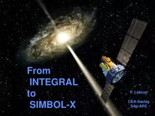
JEM-X and INTEGRAL. Niels Lund Danish National Space Center. JEM-X and INTEGRAL.

JEM-X and INTEGRAL
E N D
Presentation Transcript
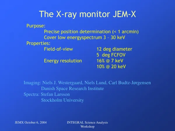
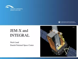
JEM-X and INTEGRAL Niels Lund Danish National Space Center
JEM-X and INTEGRAL • Originally, the decision to include an X-ray monitor in the INTEGRAL payload was done to extend the energy coverage of the gamma-ray instruments from the regime dominated by non-thermal processes down into the regime where thermal emission plays a major rôle. It was also considered important to assure a good overlap with the energy range exploited by the grazing incidence telescope missions like XMM and Chandra. • The extension of the energy-range remains the major rôle for JEM-X also today, even after considerable modifications of the originally planned gamma-ray instruments have been implemented. • An additional benefit from the inclusion of the X-ray monitor is the improved spatial resolution accessible to the lower energy instrument. • The following examples illustrates these points INTEGRAL Users Group | July 11, 2005 | ESTEC | page 2
JEM-X and IBIS observations of the Galactic center IBIS Belanger et al., submitted ApJ JEM-X 350 ks effective 8-14 keV 20-30 keV 30-40 keV 4.7 Ms effective 56-85 keV 40-56 keV INTEGRAL Users Group | July 11, 2005 | ESTEC | page 3
INTEGRAL observations of SN1006 4-8 keV 8-14 keV 3-4 keV JEM-X (250 ks effective observation time) Kalemci et al., in preparation IBIS (750 ks effective observation time) 20-40 keV INTEGRAL Users Group | July 11, 2005 | ESTEC | page 4
SN1006, preliminary conclusions: • The results obtained with INTEGRAL are consistent with earlier results obtained with ASCA, Chandra and XMM. • However, mapping diffuse emission with the INTEGRAL (coded mask-) instruments is very complex and the software and analysis method does not yet provide sufficient sensitivity to detect a bremsstrahlung component from SN1006 above 10 keV. • Further observations of SN1006 will be done in the current observation cycle. Kalemci et al., in preparation INTEGRAL Users Group | July 11, 2005 | ESTEC | page 5
Two of the three Gamma-Ray Bursts localized by JEM-X in May GRB 050502 GRB 050504 INTEGRAL Users Group | July 11, 2005 | ESTEC | page 6
The dither patterns – a practical complication. • Point source observations which relies on continous JEM-X coverage must be executed using the hexagonal dither pattern (or staring). If the 5×5-point dither pattern is used the central source will only be marginally visible for 12 of the 25 points and practically invisible for the 4 extreme corner points. Only the 9 pointings in the central 3×3 field will provide good JEM-X coverage. Unfortunately the situation is reversed for SPI for which observations in staring mode or with hexagonal dither are of little use. • A compromise has been reached by the INTEGRAL Science Working Team for TOO observations for which the default observation plan now calls for an initial hexagonal dither (7 pointings) followed by 5×5-point dither patterns for the remaining observation time. • In hindsight the discrepancy between the field of views of the monitor instruments (JEM-X and OMC) and the gamma-ray instruments (IBIS and SPI) should have been given more attention during the design phase. INTEGRAL Users Group | July 11, 2005 | ESTEC | page 7
Technical considererations. • Both JEM-X instruments on INTEGRAL are functional. Two issues have caused concern, but both now seems to be under control. 1) We have noticed that the energy resolution of the instruments slowly degrade during use, and we have decided to operate with only one instrument at a time. JEM-X unit 2 was operated from November 2001 until May 2003 and JEM-X unit 1 from May 2003 until present. • Shortly after launch it was realized that the anodes on the microstrip plates were eroded by sparks provoked by heavily ionizing cosmic rays. Initially the erosion rate was about 0.5 % per day! The rapid erosion was halted by lowering the detector voltage and reducing the gas gain by a factor 3. The erosion rate immediately dropped by a factor 50 and by now is reduced to an insignificant level. But the reduced gas gain has caused difficulties for the modelling of the detector response at low energies. Improving the modelling of this effect is now the highest priority for future updayes of the user software. INTEGRAL Users Group | July 11, 2005 | ESTEC | page 8
JEM-X status: Detector Resolution The energy resolution degrades slowly. For JEM-X1 the resolution is now 10.5% at 22 keV compared to 9% just after launch. The degradation proceeds at a slower pace in JEM-X1 than previously seen in JEM-X2 JEM-X1 JEM-X2 INTEGRAL Users Group | July 11, 2005 | ESTEC | page 9
JEM-X status: Anode Loss status • JEM-X1: Anodes lost during fabrication: 3 After 8 days of use: 10 After 3 years in space: 31 No anodes lost since December 2004! • JEM-X2: Anodes lost during fabrication: 9 After 8 days of use: 20 After 3 years in space: 36 INTEGRAL Users Group | July 11, 2005 | ESTEC | page 10
Crab calibration results During the Crab calibration executed in March 2005 a special 19 point dither pattern matched to the JEM-X mask pattern was performed, i.e. a hexagonal pattern with a pitch of 3.35 arcmin. The purpose was to illuminate (almost) all detector pixels from (almost) on-axis directions where the effects of collimator shadowing are minimized. We are using these data to understand and describe in detail the detector spatial resolution and background. These are currently the limiting factors for the JEM-X sensitivity. INTEGRAL Users Group | July 11, 2005 | ESTEC | page 11
Crab calibration The left figure shows the co-added shadowgram from the 19 close pointings. The right figure shows the corresponding illumination model (minus collimator modelling) INTEGRAL Users Group | July 11, 2005 | ESTEC | page 12
Crab calibration – collimator shadows 3-4 keV 8-14 keV 4-8 keV X-direction Y-direction Observed shadows cast by the collimator ribs during Crab close dither. Data folded with collimator pitch (7.05 mm), two periods are shown. The position resolution improves with increasing energy, but is markedly worse in the X-direction (probably due to broken anodes) INTEGRAL Users Group | July 11, 2005 | ESTEC | page 13
Mapping systematic errors as function of amplifier phase INTEGRAL Users Group | July 11, 2005 | ESTEC | page 14
Main issues for future OSA software developments: • The extraction of source fluxes from JEM-X data with the OSA-5 ”Spectral Extraction” or ”Imaging” tools are still beset with significant systematic uncertainties (±25%) when comparing observations throughout the mission. The variations show common trends between different software packages and therefore appear to be rooted in common deficiencies in the underlying instrument models. • The residual structure in the background of our sky images is still the limiting factor for our sensitivity to point sources and for ability to analyze emission from diffuse sources like supernova remnants and clusters of galaxies. INTEGRAL Users Group | July 11, 2005 | ESTEC | page 15
Outlook for the future performance of JEM-X: • Barring catastrophic failures JEM-X will be able to continue to support the INTEGRAL mission for many years. There are no signs of leakage of the detectors and no signs of gas contamination. The major concern is the gradual loss of energy resolution, however this is a relatively slow effect and is affecting the iron-line region only marginally at present. INTEGRAL Users Group | July 11, 2005 | ESTEC | page 16