Microclimate Control System
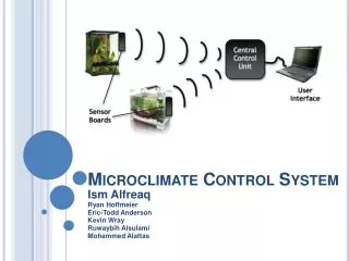
Microclimate Control System. Ism Alfreaq Ryan Hoffmeier Eric-Todd Anderson Kevin Wray Ruwaybih Alsulami Mohammed Alattas. Project overview. Develop a climate control system for easy maintenance of multiple terrariums/aquariums

Microclimate Control System
E N D
Presentation Transcript
Microclimate Control System Ism Alfreaq Ryan Hoffmeier Eric-Todd Anderson Kevin Wray RuwaybihAlsulami Mohammed Alattas
Project overview • Develop a climate control system for easy maintenance of multiple terrariums/aquariums • Easy to use user interface with possible extensions to the internet • Monitor various aspects of the environments with sensors • Control environments autonomously • Presentation of current system status on LCD screens • Possible extension to larger environment • Room in house, indoor stadium, bio-dome Mohammed Alattas
Objectives • Monitor and control environmental variables • Temperature (heaters/fans) • Humidity (mister) • Lighting (lamps) • CO2 (CO2 tanks) • Multiple sensor boards to monitor individual environments • Display current status on LCDs • Easy to use user interface via local computer • Interchangeability of peripheral devices Mohammed Alattas
Level 0 Microclimate Control System Climate Variables Mohammed Alattas Climate Control Power User Interface
Level 1 User Interface Climate Values Ryan Hoffmeier Sensor Boards Central Control Unit ClimateVariables Desired Values 12VDC, 1A PeripheralControl 6VDC, 1A Power Supply Peripheral Devices ClimateControl 120VAC Power
Level 1.1 Ryan Hoffmeier Level 1.2
Level 1.3 Ryan Hoffmeier Level 1.4
Level 2.1: Sensor Boards Sensors Ruwaybih Alsulami ClimateVariables CO2 Light Temp/Humid 5V Regulator 3.3V Regulator 6VDC, 1A I/O LCD ATMega328 Wi-Fly RS232 DesiredValues Digital/Analog I/O Climate Values Peripheral Control
Level 2.2: Peripheral Devices Heater Heat Ruwaybih Alsulami Fans Cooling/AirCirculation 120VAC(Relay Controlled) Lights ClimateControl Light Humidifier Humidity Solenoid Valve CO2 Level
Level 2.3: Central Control Unit Ruwaybih Alsulami Wi-Fly Climate Values Desired Values RS232 5VDC RCM3400 Dev Board RS232 12VDC User Interface
Level 2.4: Power Supply Sensor Board CCU Eric Anderson 6V Wall Wart 12V Wall Wart 120VAC Peripheral Relay Control System 12V Power Supply Power Strip 120VAC toPeripherals Relays PeripheralControl
Software Flow Diagram (CCU) ‘S’tatus ‘P’rogram Root Eric Anderson ‘Q’uit ‘Q’uit choose tank # choose tank # or all ‘tank #’ ‘tank #’ ‘Q’uit choose variable to set ‘A’ll ‘Q’uit get status for tank # ‘Q’uit get status for all set variable
Software: Sensor Board Pseudo Code Loop: check sensor 1 if out of range: adjust peripheral check sensor 2 if out of range: adjust peripheral check sensor 3 if out of range: adjust peripheral check uart connected to WiFly (CCU) if new parameters: change climate variables return current climate status Eric Anderson
System Block Diagram Sensor Board 1 Sensor Board 2 Light Sensor Light Sensor Kevin Wray Temp. Sensor Temp. Sensor WiFly Humidity Sensor Humidity Sensor User Interface (PC) Central Control Unit CO2 Sensor CO2 Sensor CO2 Tank CO2 Tank Lights Lights Heater Heater WiFly Fans Fans Network Humidifier Humidifier LCD Output LCD Output
Control unit microprocessor: RCM3400W • Rabbit 3000 microprocessor 30MHz • 8 channel 12-bit A/D with programmable gain • Up to 47 I/O lines and 5 serial ports • 412K Flash/512K SRAM Kevin Wray
Sensor board microcontroller:ATMega328 • 1.8-5.5V operating range • Serial USART • 32kB Flash program memory • 1kB EEPROM (non-volatile) • 2kB Internal SRAM • Up to 20MHz Kevin Wray
ATMega328 Pinout Eric Anderson
WiFly Communication • Central Control Unit communicates wirelessly with sensor boards using WiFly • RN-134 “SuRF” board Eric Anderson
Sensors • MG811 – CO2 Sensor • Detects 0.035% to 1% • Low humidity and temperature dependency • Needs ADC Mohammed Alattas • SHT71 – Humidity and Temperature Sensor • Normal operating range: -20–100oC • Digital output • Low power consumption • TSL235R – Light Sensor • Light to frequency converter • 350–1000nm • Output frequency: 200–300kHz
Peripherals • Solenoid valve (CO2) • Fans • Lights • Mister • Heater Mohammed Alattas
Power (Sensor Boards) Ryan Hoffmeier 5VDC 3.3VDC 6VDC 120VAC CO2 Sensor (200mA) Wi-Fly (210mA) ATMega328 (200mA) Light Sensor (2mA) UART to USB (20mA) T/H Sensor (1mA) LCD Screen (3mA)
Power • Largest power usage through peripherals • Sensor board connected to opto-isolator • Isolator allows relay to pass current • Keeps high current levels off of sensor boards • Isolation of individual outlets of a power strip • Allows for easy exchange of peripherals Ryan Hoffmeier
Parts List Kevin Wray
Division of Labor Kevin Wray
Schedule Ruwaybih Alsulami
Schedule Highlights • Milestone I • Parts interfaced with Arduino board • Power strip control boards completed • Milestone II • Sensor boards completed • Sensor boards interface with CCU • User interface completed • Expo • Documentation completed • Expansions? Ruwaybih Alsulami