Shift Registers - Operations and Applications
Explore the functions and applications of shift registers in digital systems. Learn about loading, data transfer methods, serial and parallel shifting operations, clock edge requirements, and various shift register configurations. Discover how shift registers are used in serial/parallel and parallel/serial conversion for serial communication.


Shift Registers - Operations and Applications
E N D
Presentation Transcript
CHAPTER 4 SHIFT REGISTER Chapter 1
Introduction: Registers • An n-bit register has a group of n flip-flops and some logic gates and is capable of storing n bits of information. • The flip-flops store the information while the gates control when and how new information is transferred into the register. • Some functions of register: • retrieve data from register • store/load new data into register (serial or parallel) • shift the data within register (left or right) Chapter 1
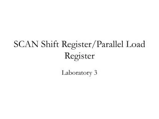
Loadinga register: transfer new information into the register. Requires a load control input. • Parallel loading: all bits are loaded simultaneously. Chapter 1
Combinations of Data Transfer Methods 10110 10110 • SISO: Serial In, Serial Out • SIPO: Serial In, Parallel Out 10110 10110 Chapter 1 How many clock edges are required for each operation? Registers 1.4
Combinations of Data Transfer Methods • PISO: Parallel In, Serial Out • PIPO: Parallel In, Parallel Out 10110 Chapter 1 10110 10110 10110 How many clock edges are required for each operation? Registers 1.5
4 Bit Serial Shift left Register Step 1, Q3,Q2Q1,Q0 = 0001
4 Bit Serial Shift left Register Step 2: Q3,Q2Q1,Q0 = 0011
4 Bit Serial Shift left Register Step 3 : Q3,Q2Q1,Q0 = 0111
4 Bit Serial Shift left Register Step 4: Q3,Q2Q1,Q0 = 1111
4 Bit Serial Shift Right Register 4-bit Serial-in to Serial-out Shift Register
4 Bit Serial Shift Right Register Step 1: Q3,Q2Q1,Q0 = 1000
4 Bit Serial Shift Right Register Step 1: Q3,Q2Q1,Q0 = 1100
4 Bit Serial Shift Right Register Step 1: Q3,Q2Q1,Q0 = 1110
4 Bit Serial Shift Right Register Step 1: Q3,Q2Q1,Q0 = 1111
4 Bit Parallel In Serial Out Shift Register (PISO) Load mode: Load mode s active low device, they gives s/g to AND gate 2,4,6 & they become active. They pass B0,B1,B2,B3 bits to the corresponding flipflops. On the low going edge of clock the binary inputs B0,B1,B2,B3 will get loaded into the corresponding flipflops. Thus parallel loading is take place.
4 Bit Parallel In Serial Out Shift Register (PISO) Shift mode: Shift mode is active high device, they gives s/g to AND gate 1,3,5 & they become active at that time AND gate 2,4,6 become inactive. Hence parallel loading is not possible therefore data shifting of data from left to right, bit by bit.
4 Bit Serial In Parallel Out Shift Register (SIPO) In this operation the data is entered serially and taken out parallel. First data is loaded bit by bit Loading is complete after that o/p are enable No. of clock pulse require to load a four bit word is 4.
4 Bit Parallel In Parallel Out Shift Register (PIPO) 4-bit Parallel-in to Parallel-out Shift Register
4 Bit Parallel In Parallel Out Shift Register (PIPO) The 4 bit binary input B0,B1,B2,B3 is applied to the data input D0,D1,D2,D3 respectively. A negative clock pulse is applied the binary input will be loaded into flip flop simultaneously and loaded bit will appear at o/p side. Only one clock pulse is essential to load all the bits.
4 Bit Bi-directional Shift Register M=1= Shift right operation M=1 then AND gate 1,3,5,7 are enabled whereas the remaining AND gate 2,4,6,8 will be disable. Data DR shifted bit by bit from FF3 to FF0, on the application of clock pulse. M=0=Shift left operation M=0 then AND gate 2,4,6,8 are enabled whereas the remaining AND gate 1,3,5,7 will be disable. Data DL shifted bit by bit from FF0 to FF3, on the application of clock pulse. M changed only when clock =0 otherwise data stored in the register may be altered.
Universal Shift Register This shift register is capable of performing the following operations Parallel loading Left shifting Right shifting
An application of a shift register in serial/parallel and parallel/serial conversion used in serial communication. Chapter 1