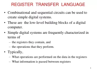
Chapter 4 Register Transfer and Microoperations
Chapter 4 Register Transfer and Microoperations . Dr. Bernard Chen Ph.D. University of Central Arkansas Spring 2009. Outline. Bus Transfer Memory Transfer Microoperations. This Chapter contains. A basic computer: 1. The set of registers and their functions;


Chapter 4 Register Transfer and Microoperations
E N D
Presentation Transcript
Chapter 4 Register Transfer and Microoperations Dr. Bernard Chen Ph.D. University of Central Arkansas Spring 2009
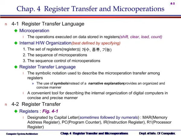
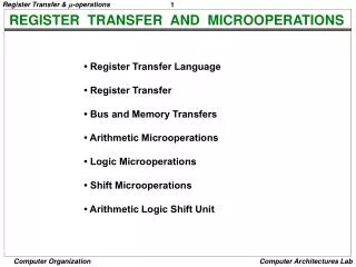
Outline • Bus Transfer • Memory Transfer • Microoperations
This Chapter contains • A basic computer: • 1. The set of registers and their functions; • 2. The sequence of microoperations; • 3. The control that initiates the sequence of microoperations
Register Transfer Data can move from register to register. Digital logic used to process data for example: Register A Register B Register C Digital Logic Circuits C A + B
Building a Computer Needs: processing storage communication
Multiplexer-Based Transfer for TWO 4-bit registers 0 1 Use of Multiplexers to Select between Two Registers
Bus Transfer • For register R0 to R3 in a 4 bit system 4-line common bus S1 S0 Register D Register C Register B Register A Used for lowest bit Used for highest bit from each register
Question • For register R0 to R63 in a 16 bit system: • What is the MUX size we use? • How many MUX we need? • How many select bit?
Three-State Bus Buffers • A bus system can be constructed with three-state gatesinstead ofmultiplexers • Tri-State : 0, 1, High-impedance(Open circuit) • Buffer • A device designed to be inserted between other devices to match impedance, to prevent mixed interactions, and to supply additional drive or relay capability
Tri-state buffer gate • Tri-state buffer gate : Fig. 4-4 • When control input =1 : The output is enabled(output Y = input A) • When control input =0 : The output is disabled(output Y = high-impedance) Normal input A If C=1, Output Y = A If C=0, Output = High-impedance Control input C
The construction of a bus system with tri-state buffer A0 B0 C0 D0 Select input Enable input
Memory Transfer • The transfer of information from a memory word to the outside environment is called a read operation • The transfer of new information to be stored into the memory is called a write operation
Memory Read and Write • AR: address register • DR: data register Read: DR M[AR] Write: M[AR] R1
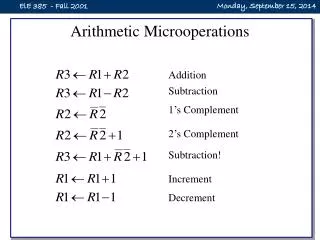
Symbolic designation Description R3 ← R1 + R2 Contents of R1 plus R2 transferred to R3 R3 ← R1 – R2 Contents of R1 minus R2 transferred to R3 R2 ← R2 Complement the contents of R2 (1’s complement) R2 ← R2 + 1 2’s Complement the contents of R2 (negate) R3 ← R1 + R2 + 1 R1 plus the 2’s complement of R2 (subtract) R1 ← R1 + 1 Increment the contents of R1 by one R1 ← R1 – 1 Decrement the contents of R1 by one Arithmetic Microoperations • Multiplication and division are not basic arithmetic operations • Multiplication : R0 = R1 * R2 • Division : R0 = R1 / R2
Arithmetic Microoperations • A single circuit does both arithmetic addition and subtraction depending on control signals. • • Arithmetic addition: • R3 R1 + R2 (Here + is not logical OR. It denotes addition)
Arithmetic Microoperations • Arithmetic subtraction: • R3 R1 + R2 + 1 • where R2 is the 1’s complement of R2. • Adding 1 to the one’s complement is equivalent to taking the 2’s complement of R2 and adding it to R1.
BINARY ADDER • Binary adder is constructed with full-adder circuits connected in cascade.
BINARY ADDER-SUBTRACTOR • The addition and subtraction operations cane be combined into one common circuit by including an exclusive-OR gate with each full-adder. XOR M b 0 0 0 0 1 1 1 0 1 1 1 0
BINARY ADDER-SUBTRACTOR • • M = 0: Note that B XOR 0 = B. This is exactly the same as the binary adder with carry in C0 = 0. • M = 1: Note that B XOR 1 = B (flip all B bits). The outputs of the XOR gates are thus the 1’s complement of B. • M = 1 also provides a carry in 1. The entire operation is: A + B + 1.
4-bit Binary Incrementer • Adds one to a number in a register • Sequential circuit implementation using binary counter • Combinational circuit implementation using Half Adder • The least significant HA bit is connected to logic-1 • The output carry from one HA is connected to the input of the next-higher-order HA
4-bit Binary Incrementer B3 B2 B1 B0 1 Always added to 1 C4 S3 S2 S1 S0