Download
1 / 27
270 likes | 300 Views
This presentation from the 9th Vienna Conference on Instrumentation in February 2001 covers the design and components of the ATLAS Silicon Microstrip Tracker (SCT) for the Large Hadron Collider at CERN. The discussion includes system design, sensors, module design, and electronics hybrids for the ATLAS SCT collaboration. Details such as the performance, radiation environment, and specific components like sensors, modules, and front-end chips are explored. The talk addresses the challenges of high luminosity, radiation hardness, and particle tracking efficiency at the LHC.

E N D
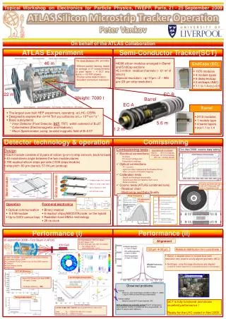
9th Vienna Conference on Instrumentation, February 2001 The ATLAS Silicon Microstrip Tracker Lutz Feld, Freiburg University, for the ATLAS SCT Collaboration introduction system design sensors module design electronics hybrids status
Large Hadron Collider at CERN • pp collisions at 14 TeV centre of mass energy • two multi purpose experiments: ATLAS and CMS • two specialised experiments: ALICE (heavy ions) and LHC-B (b physics and CP) • first beam in 2005, first collisions in 2006 Vienna Conference on Instrumentation, Feb. 2001
46m 22m ATLAS-Detector Vienna Conference on Instrumentation, Feb. 2001
LHC means high rate and high multiplicity at full luminosity L=1034 cm-2 s-1: • ~23 overlapping interactions in each bunch crossing every 25 ns ( = 40 MHz ) • inside tracker acceptance (|h|<2.5) 750 charged tracks per bunch crossing • per year: ~5x10¹⁴ bb; ~1014 tt; ~20,000 higgs; but also ~1016 inelastic collisions • severe radiation damage to detectors • detector requirements: speed, granularity, radiation hardness a H->bb event a H->bb event as observed at high luminosity plus 22 minimum biasinteractions Vienna Conference on Instrumentation, Feb. 2001
ATLAS Inner Tracker • Performance: • rapidity coverage: || < 2.5 • momentum resolution for isolated leptons:pT/ pT ~0.1 pT (TeV) • track reconstruction efficiency (high-pT) • for isolated tracks > 95%, within jests > 90%, • ghost tracks < 1% (for isolated tracks) • impact parameter resolution at high-pT r- < 20 m, z < 100 m • low material budget for tracker and ECAL performances • lifetime> 10 LHC years 7m 2.3m inside a solenoid providing 2T magnetic filed Vienna Conference on Instrumentation, Feb. 2001
ATLAS Silicon Microstrip Tracker SCT • 4 barrel layers • barrel radii: 300, 371, 443 and 514 mm; length 1600 mm • in total 2112 modules • 2 x 9 forward disks • disk distance from z = 0: 835 - 2788 mm, radii: 259-560 mm • in total 1976 modules (3 rings: 40, 40, 52 modules each) • all 4088 modules double sided • 15,392 sensors of total 61.1m² • total length of diode: 716 km • 49,056 front-end chips, total 6.3 Mio. channels • optical command and data links 1.2m 5.6m Vienna Conference on Instrumentation, Feb. 2001
Radiation Environment • in SCT volume up to 1.3x10¹⁴ 1-MeV-n/cm²and 5 Mrad for10 years of operation • damage to sensors • bulk damage: displacement of Si atoms from lattice sites • increasing leakage current Ileak~fluence • inversion from n-type to p-type and depletion voltage changes, increasing up to ~300V • deterioration of charge collection • surface damage: creation of charge carriers in silicon oxide • modification of electron accumulation layer and change of interstrip capacitance • damage to electronics • modification of oxide charge changes threshold voltages of MOS transistors • mid-gap states degrade current gain in bipolar transistors • parasitic currents • single event upset Vienna Conference on Instrumentation, Feb. 2001
ATLAS SCT Sensors • p-on-n single sided detectors • 285µm thick • 2-8 kW.cm • 4“ substrate • barrel • 64x64mm² • 80µm pitch • forward • 5 different wedge shaped sensors • radial strips • 50...90µm pitch • 768 read-out strips • AC coupled to read-out • polysilicon or implanted resistors • multiguard structure for HV stability • ~20000 sensors needed • ordered from Hamamatsu, CIS (and Sintef) Vienna Conference on Instrumentation, Feb. 2001
Leakage Current after Irradiation • IV curves for CiS wedge detectors after 3x10¹⁴ p/cm2 (7 days annealing at 25°C) • Spec: <250 µA at 450V and -18°C MPI/HLL Vienna Conference on Instrumentation, Feb. 2001
Depletion Voltage after Irradiation • beneficial annealing: few days at room temperature decreases depletion voltage • reverse annealing: longer time at temperatures >0°C increases depletion voltage • -> need to keep irradiated silicon cold (<0°C) • oxigenated detectors: less damage and slower reverse annealing,will be used in parts of the inner region MPI Munich Vienna Conference on Instrumentation, Feb. 2001
Barrel Modules • double sided module as back-to-back build-up of 2 pairs of rectangular sensors • 40 mrad stereo angle to measure second co-ordinate • centre-tapped electronics hybrid Vienna Conference on Instrumentation, Feb. 2001
SCT Forward Disk cooling block power tapes optical fibres outer modules middle modules(on backside) inner modules Vienna Conference on Instrumentation, Feb. 2001
Forward Module in Transport Frame Vienna Conference on Instrumentation, Feb. 2001
Forward Module • double sided module as back-to-back build-up of 2 pairs of wedge shaped sensors • 40 mrad stereo angle to measure second co-ordinate • double sided, end-tapped electronics hybrid • alignment: 4µm sensor-to-sensor on each side, 8µm front-to-back Vienna Conference on Instrumentation, Feb. 2001
Leakage Current and Thermal Stability • Ileak = a x volume x fluence • a 3x10-17 A/cm at 20 oC, fluence in 1MeV equiv. • independent of material or radiation type • after 10 years of LHC running: • a 12 cm long strip at 100 mm pitch draws ~1 µA, • a detector module (160 cm2) draws ~2mA,(both at -10 oC). • given the high bias voltage this leads to a significantpower dissipation of the silicon itself-> need efficient cooling to avoid thermal runaway • remedies: • leakage current strongly temperature dependent • I=I0 T2 exp(-Eg/kT) • current doubles every 7°C • thermal split between hybrid and sensors • reduce thermal resistance in the module • C3F8 evaporative cooling system at ~ -20°C,keeping silicon temperature around -7°C expected power dissipationafter 10 years Vienna Conference on Instrumentation, Feb. 2001
Front-End ASIC ABCD3T • binary read-out • 128 channels • DMILL radiation hard process • bipolar input transistor • shaping time ~20ns • comparator threshold trimmable for each channel • 132 cell pipeline • edge detection, data reduction and multiplexing • expected ENC ~ 1500 e for 12 cm strips, increasing to ~1800 e after 10 years of irradiation • ~4 mW/channel digital analogue control logic 128 channels read-out buffers comparator preamp data reduction pipeline shaper Vienna Conference on Instrumentation, Feb. 2001
Forward Electronics Hybrid • requirements: • double sided • distribute and filter analogue and digital currents (~4V, 1.8A) • route/filter detector bias (500V) • filter/shield noise/pick-up • route commands and data • full redundancy • provide electrical/optical connectivity • remove heat (~7.2W) • low mass • implementation: • 4 layers of copper traces in Kapton flex • trace width/gap ~75µm • layer thickness ~15µm • ~3000 micro vias for connections between planes • produced at DYCONEX AG • flex folded around a metallised carbon fibre substrate • similar technology used for barrel hybrid Vienna Conference on Instrumentation, Feb. 2001
System Test: Forward Mini-Sector Bench: 3 outer modules power cables Sector: inner module optical fibres with proper grounding schemeno extra noise on the disk Vienna Conference on Instrumentation, Feb. 2001
Test Beam: Median Charge Collection vs. Bias Voltage non-irradiated module full module irradiatedto 3x10¹⁴p/cm2 analysis: N. Unno PRELIMINARY uncertainty on charge calibration is about 20% Vienna Conference on Instrumentation, Feb. 2001
Test Beam: Hit Efficiency and Noise Occupancy efficiency at 1 fC vs. bias voltage noise occupancy vs. threshold non-irradiated module full module irradiated to 3x10¹⁴p/cm2 full module irradiated to 3x10¹⁴p/cm2 non-irradiated module analysis: N. Unno PRELIMINARY Vienna Conference on Instrumentation, Feb. 2001
Production Scheme • distributed, parallel production • module production (2001-2003): • barrel: KEK, RAL, Berkeley, Oslo • forward: Manchester, Valencia, Geneva, MPI, Freiburg, Prague, NIKHEF, Melbourne • mounting modules onto structures (2001 -2003): • barrel:KEK, Oxford • forward:Liverpool, NIKHEF, Melbourne • macro-assembly (2003 -2004): • integration of 4 barrels at CERN • mounting of disks into support cylinders at NIKHEF and CERN/UK • SCT ready for installation in ATLAS: 2004 Vienna Conference on Instrumentation, Feb. 2001
Summary and Current Status • the ATLAS SCT is now preparing the production phase • sensors are under fabrication • front-end electronics chosen and pre-production has started • electronics hybrids close to final design review • module design close to final design review • several close-to-final modules built and tested (incl. irradiation) • module assembly procedure defined and production centres in qualification step • off-detector electronics and services in prototyping • cooling tested on prototypes • barrel support structure under construction • forward support structure in prototyping Vienna Conference on Instrumentation, Feb. 2001
ATLAS Inner Tracker Vienna Conference on Instrumentation, Feb. 2001
Charge Collection Efficiency sensors irradiated to 3x10¹⁴ 24GeV-p/cm2 standard material oxygenated material signal seen on single strip with ~20ns shaping after 32 days annealing at 25°C (MPI Munich) Vienna Conference on Instrumentation, Feb. 2001
SCT Material Budget Vienna Conference on Instrumentation, Feb. 2001
Magnetic Field and pt Resolution • pt resolution as a function of |h| for muons of various momenta • circles and squares show simulation for ATLAS solenoidal field, triangles for uniform field Vienna Conference on Instrumentation, Feb. 2001
Impact Parameter Resolution Vienna Conference on Instrumentation, Feb. 2001