Download
1 / 12
120 likes | 417 Views
A High Density Carbon Nanotube Capacitor for Decoupling Applications. Mark M. Budnik, Arijit Raychowdhury, Aditya Bansal, Kaushik Roy July 27, 2006. A High Density Carbon Nanotube Capacitor. Introduction to Decoupling Capacitors Carbon Nanotube Capacitor Physical Structure

E N D
A High Density Carbon Nanotube Capacitor for Decoupling Applications Mark M. Budnik, Arijit Raychowdhury, Aditya Bansal, Kaushik Roy July 27,2006
A High Density Carbon Nanotube Capacitor • Introduction to Decoupling Capacitors • Carbon Nanotube Capacitor Physical Structure • Carbon Nanotube Electrical Model • Carbon Nanotube vs. Conventional Capacitors • Capacitance per Unit Area • Leakage per Unit Area • Conclusions
Introduction to Decoupling Capacitors • Decoupling capacitors are used to reduce supply voltage variations in advanced processors + Input Voltage i (t) -
Traditional Decoupling Capacitors • Problems • Parallel plate topology - low capacitance / unit area • Expensive die area • High leakage current • Algorithm placement • Improvements? • Improve dielectric material - limited • Increase area - more expensive, more leakage • Decrease dielectric thickness - more leakage • Increase number of layers - unproven
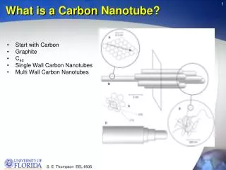
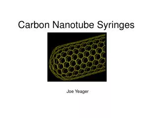
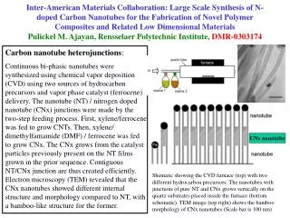
Carbon Nanotube Capacitor Alternative • Metallic, single wall carbon nanotubes • Offer large surface area to volume ratio ~ 1nm ~ 1nm 1m
Carbon Nanotube Capacitor (CNCAP) C C A A C = Cathode A = Anode C C A A C C A A C C A A
CNCAP Electrical Model Parallel CNTs CNCAP Model R/2 L/2 L/2 R/2 Cathode End Front CQ CQ L CG CC CQ CT R/2 L/2 L/2 R/2 End Front R CQ CG Anode
Capacitance Per Unit Area Separation 2 nm 3 nm 4 nm CC 22.8 aF / µm 18.1 aF / µm 15.6 aF / µm CT 20.4 aF / µm 16.6 aF / µm 14.4 aF / µm 4xCT 81.6 aF / µm 66.4 aF / µm 57.6 aF / µm Capacitor Technology 2018 MOS CNCAP, s=2nm CNCAP, s=3nm CNCAP, s=4nm ITRS Capacitance ( fF / µm2 ) 11 - - - - - - - - - 200 CNT Layers Capacitance ( fF / µm2 ) - - - 2,710 1,660 1,160
Capacitance Leakage Per Unit Area ILEAK Capacitor Technology 2018 MOS CNCAP, s=2nm CNCAP, s=3nm CNCAP, s=4nm Capacitance ( fF / µm2 ) 11 2,710 1,660 1,160 Leakage Current ( / µm2 ) < 20 fA 1.83 µA 27.5 pA 0.586 fA
Conclusions • Traditional MOS parallel plate capacitors • Limited in ability to serve as decoupling capacitors • Limited improvements for the forseeable future • Metallic, single wall carbon nanotubes • High surface area to volume ratio • Small inter-tube spacing can result in appreciable capacitance per unit length • May be placed in multiple layer bundles • 3-D carbon nanotube capacitor structure • High capacitance per unit area ( >> 11fF / µm2 as a function of the number of layers) • Low leakage current per unit area ( < 1fA / µm2 for inter-tube spacing of 4nm)