Download

1 / 24
770 likes | 2.46k Views
Carbon Nanotube Transistors . By Paul Baumstarck, Miguel Taveras, and Andrew White. Overview. Background Major contributors Benefits of CNFETs Difficulties and problems with CNTs The future of carbon CNTs. What is a carbon nanotube?.

E N D
Carbon Nanotube Transistors By Paul Baumstarck, Miguel Taveras, and Andrew White
Overview • Background • Major contributors • Benefits of CNFETs • Difficulties and problems with CNTs • The future of carbon CNTs
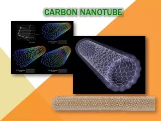
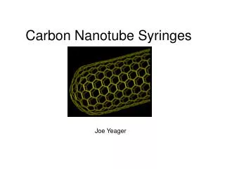
What is a carbon nanotube? A carbon nanotube is a graphene sheet (with carbon atoms appearing in a hexagonal pattern) rolled up to form a hollow cylinder. CNTs have extremely low electrical resistance because electrons can travel for large distances without scattering (ballistic transport). This is partly due to their very small diameter and huge ratio of length to diameter. Also, because of their low resistance, CNTs dissipate very little energy. This will prove useful in solving the power consumption problems that are plaguing Silicon circuits.
Carbon nanotube formation Graphene Sheet Semiconductor Types E-k Relations The vector C in the figure above is the vector normal to the circumference vector in the direction the tube is rolled. C = na1 + ma2 gives the vector C. The values for the scalars n and m determine whether the nanotube is conducting or semi-conducting.
MOSFETs: The End of an Age • Past 40 years MOSFETs have been most widely used technology. • Latest technology MOSFET has minimum feature of 0.25 micron. • Quantum mechanics and fabrication techniques are limiting minimum feature size. • New nano-devices will take advantage of quantum mechanical phenomena which was previously ignored.
Carbon Nanotube Field Effect Transistor • In the generic CNFET a carbon nanotube is placed between two electrodes while a separate gate electrode controls the flow of current in the channel. Basic CNFET Design Actual CNFET
Three Basic CNFET Designs • Two common designs: • Coaxial Shottky-Barrier CNFETs • MOSFET-like CNFETs Ambipolar I-V Behavior
P- and N-Type CNTs • CNTs are naturally p-type because exposure to the oxygen in the air causes the Fermi level to shift towards the valence band. However, there are several methods available to convert p-type CNTs to n-type: • Annealing in vacuum or H2 • Doping with Potassium P- and N-Type CNFET I-V Plots
Single-Electron CN Transistor Researches at Delft University in the Netherlands created the world’s first single-electron transistor by placing two sharp bends (i.e., large potential barriers) in a CNT 20 nm apart to create a “conducting island” that electrons must tunnel in to. Bending of a Single Walled Carbon Nanotube SET and “Conducting Island”
Circuit Example: CNFET Inverter CNFETs have already been used to implement basic logic circuits such as the inverter. CNFET Inverter and Voltage Transfer Characteristic
Major Contributors: Sumio Iijima • A leading researcher at NEC Laboratories since the late 1980’s. • Discovered carbon nanotubes in 1991 by demonstrating that the carbon fibers produced by a carbon arc were hollow. • Also showed how to produce “nanohorns” at room temperature and with high yield (nanohorns had been previously discovered by Peter Harris). Nanohorns have since proven useful in next-generation fuel cells because they have very high absorbability. Nanohorn Nanohorn Bundle
Major Contributors: NEC laboratory • One of the biggest and longest- standing corporation laboratories in nanotube research. • Have used nanohorns to produce small fuel cells for mobile applications. • Are active in CNFET design: • They have developed a stable fabrication technology for CNT transistors, and transistors produced with this process have demonstrated more than 10 times the transconductance of silicon MOS transistors. • One of NEC’s future research goals is to replace the bulky metal electrodes of their CNFETs with other nanotubes such as Boron-Nitride.
Major Contributors: IBM • IBM has used CNTs and their ambipolar characteristics to produce nanotube light sources. One prototype used a 1.4-nm diameter nanotube to produce light through the collision of holes and electrons. Varying the gate voltage also controlled where along the length of the CNT the light was emitted. Nanotube Light Varying the Light Emission Point
Major Contributors: IBM (Cont.) Const. Deconst. Process Diagram Constructive Deconstruction: IBM developed a method for controlling which kinds of nanotubes are deposited on the substrate. Originally, both metallic and semiconducting CNTs are grown, then electrodes are placed across the bundles. A high voltage is applied across the electrodes which destroys the metallic CNTs but leaves the semiconducting ones intact.
Major Contributors: UBC This group of researches has written many influential papers on the characteristics of SB-CNFETs including “Electrostatics of Coaxial Shottky-Barrier Carbon Nanotube Field-Effect Transistors” and “Electrostatics of partially gated carbon nanotube FETs.” SB-CNFET Energy Band Diagrams D. L. John, Leonardo C. Castro, Jason Clifford, and David L. Pulfrey at the University of British Columbia, Vancouver, Canada
Benefits of CNFETs • High single crystallinity • Low defect density, grain boundary free • Predictable electron transport properties • Reliable device performance • Unique properties due to quantum confinement effects • Enhancement in device characteristics • Potential to revolutionize nano-scale science and technology
Advantages of CNTs over Silicon • As Silicon transistors are scaled down the doping of the channel has to increase proportionately while its volume decreases. The change in the number of dopants produces important differences in switching properties and degrades the overall performance of the system. • Nanotube transistors can operate even without dopants and are less sensitive to differences in the channel length. Instead, CNFETs depend on the diameter of the tube and its chirality.
CNT Challenges • The production methods available for CNTs either produce CNTs with widely varying sizes and chiralities or are prohibitively expensive. • Exposure to open air can cause an n-type CNT to revert back to p-type. • Placing CNTs on substrate is also a big challenge. Some prospective solutions are DNA Self-Assembly and using a electric field to direct CNT growth during Chemical Vapor Deposition. • The main obstacle to CNTs replacing Silicon transistors is that there are no mass production methods available for CNTs to rival the well-developed Silicon and photolithography process at present.
The Future • Medium term (5-10 years) - Memory devices - Fuel cells, batteries - Biosensors (CNT, molecular) - Biomedical devices - Advances in gene sequencing • Long term (> 15 years) - Nanoelectronics (CNT) - Molecular electronics - Use in new aerospace and automotive industry composites
Problem Statement • We examined how the tunneling probability in SB-CNFETs depends on the diameter of the nanotube and possible applications of this to electronic circuit design. Expected Energy Band Diagram for SB-CNFET with Applied Gate Voltage SB-CNFET Diagram
Application Problem (Cont.) • Assume triangular tunneling barrier as in textbook: Triangular Barrier Tunneling Equations
Application Problem (Cont.) • Results of tunneling probability calculations: 3-D Tunneling Probability vs. Energy and Diameter Tunneling Probability vs. Energy with Varying Diameter
Application Problem (Cont.) • Circuit applications: multiple-valued logic Ternary Inverter Implemented with CN-FETs Power Delay Product Comparisons for CN-FET Ternary Logic
Carbon Nanotube Devices By Paul Baumstarck, Miguel Taveras, and Andrew White