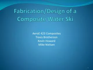
Fabrication/Design of a Composite Water Ski
Fabrication/Design of a Composite Water Ski. AeroE 423 Composites Travis Brotherson Kevin Howard Mike Nielsen. Outline. Background Design -Reverse Engineering -ANSYS Solution Fabrication -Mold -Bottom Lay-Up -Core -Top Lay-up Results Conclusion -Recommendations.

Fabrication/Design of a Composite Water Ski
E N D
Presentation Transcript
Fabrication/Design of a Composite Water Ski AeroE 423 Composites Travis Brotherson Kevin Howard Mike Nielsen
Outline Background Design -Reverse Engineering -ANSYS Solution Fabrication -Mold -Bottom Lay-Up -Core -Top Lay-up Results Conclusion -Recommendations
Background The Goode Company has been fabricating carbon fiber skis for the past decade. What is the Purpose? • Carbon fiber skis weigh less then the conventional mass-produced fiberglass water ski. • Higher flex and torsion ratios. • Carbon fiber has stronger properties then fiberglass.
Design • Reverse-Engineering -Used Faro Arm to capture x, y, and z coordinate points of an already manufactured water ski. -The coordinates were captured in a cross sectional area manner from the tip to the tail of the water ski. Each cross sectional area had its own text file. - The coordinate points were then imported into a CAD software package Solidworks to create a working image. -Imported into ANSYS by saving CAD model as an IGES file.
ANSYS Model Design Structural Aspects • Element shell 99 was used for the carbon fiber layers, with each ply being approximately .005 inches in thickness. A total of four [0/90] weave plies were used. Carbon Fiber Properties
ANSYS Model Design Cont’d • Element Solid 45 was used for the inner core of the ski. The elastic modulus of 10 Psi was used. Applied Loads/DOF • Apressure load was then placed at the bottom of the ski to represent the force that water would exert. A pressure load of .75 psi was placed along the surface of the water ski. This pressure load was used because it represents approximately a 200 lb person mounted on the ski. • The water ski was fixed at the boot mount location for all DOF.
ANSYS Model Design Cont’d The image below shows the ski structure that was tested in ANSYS. The blue line in the image show were the cross sectional area data points were taken. Cross Sectional Areas
ANSYS Model Solution The max displacement of the Water Ski with the applied pressure load was approximately .06 inches. This max displacement is occurring near the tip of the ski. The maximum stresses occur near the max deflections. Y-Direction Stress Y-Direction Displacement
Mold Goal: Obtain in accurate representation of the bottom surface of a water ski. STEPS: 1.) Make a crate to hold mold. 2.) Cutting off foam to support the top surface of ski inside the crate. 3.) Fill in voids with clay, in between ski and foam. 4.) Shillaced clay surface and waxed ski. 5.) Used mold release spray on ski and clay. 6.) Poured Plaster a Paris on bottom surface of ski.
Bottom Surface Lay-Up • A plastic tube with 1/8 inch diameter holes was than wrapped around edges of mold. The holes were set approximately 2-3 inches apart. - A plastic T-stem was then used to close of the ends of tube into one inlet, which will be hooked to vacuum line. • Release film is then placed on surface of the mold.
Bottom Surface Lay-Up • A total of four layers of carbon fiber was used. The carbon fibers plies orientation is set as [0/90] weave. A resin transfer mesh was placed on the carbon fiber layers. • A release film was wrapped around the whole surface of the mold and the vacuum tube inlet then sealed tightly. • A slit was cut into the release film were the epoxy injection tube would be placed. • The vacuum was then turned on which allowed the carbon fiber to take form with mold. • The epoxy was then steadily injected into the bag .
Bottom Surface of Ski Setup Vacuum Inlet Epoxy Inlet Plastic Vacuum Line Resin Transfer Mesh
Bottom Surface Lay-Up • After the carbon fiber had been fully cured, it was released from the mold. • Cutting and sanding was done to rid of the excess epoxy and form the shape of the edges
Core of Water Ski • Hollow PVC pipe was cut and set in place at the location where the boot mounts will be drilled. • The PVC pipe was then filled with epoxy and allowed to harden. • “Great Stuff” expandable foam was then used for the core of the ski. • The expandable foam was then sanded down after 8 hours of drying.
Internal Core of the Water Ski Epoxy Boot mount pucks Foam Core
Top Surface Lay-Up • Once the core was fully sanded, it was then layered with 4 layers of carbon fiber. • The carbon fiber layers used are a [0/90] degree weave. • The resin was hand applied for each layer of the carbon fiber material. • The carbon fiber was wrapped around the edges of the ski while each ply was layered. • Once the carbon fiber material had been completely layered, the product was bagged with release film.
Top Surface Lay-Up • A vacuum line was then attached to the release film. The vacuum was used to in the curing process of the top layer. • Once the carbon fiber was cured, it was cut, grinded and sanded to form a smooth surface.
Results For testing a three point bend test was conducted. The load was applied at the center of the ski. It was fixed 14 inches away from the tip and tail of ski. The amount of deflection was recorded with applied load. Test Stand Deflection Gage
Results The displacements of the water ski relative to the applied load were then compared to one another. In elastic modulus of 5.0 E 6 Psi was calculated for the manufactured ski, while a elastic modulus of 3.0 E 6 Psi was calculated for the carbon fiber water ski.
Conclusion • In the overall product of the water ski the elasticity was comparable to that of the already manufactured ski. • The flex of the carbon fiber ski was slightly more which would make it more forgiving in turns. • For the next iteration a stronger ski would be built, due to personal preference. The water ski would be made stronger by adding more carbon fiber layers.
Further Considerations • Making the mold out of silicon rubber to eliminate mold cracking and forming of a smoother surface. • Use a larger vacuum bag to allow the ski to form into the mold better, creating a more consistent shape. • Revise the resin transfer process to allow a more consistent thickness, perhaps more inlet ports. • Use high density foam formed for the core to eliminate porosity issues.
Acknowledgments • Dr. VinayDayal • Bill Rickard • Nathan Knop
Questions? Slalom Skiing