Download
1 / 87
940 likes | 1.27k Views
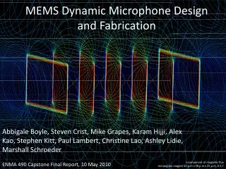
MEMS Dynamic Microphone Design and Fabrication. Abbigale Boyle, Steven Crist, Mike Grapes, Karam Hijji, Alex Kao, Stephen Kitt, Paul Lambert, Christine Lao, Ashley Lidie, Marshall Schroeder. z-component of magnetic flux rectangular magnet 50 μ m x 50 μ m x 25 μ m, 0.5 T.

E N D
MEMS Dynamic Microphone Design and Fabrication Abbigale Boyle, Steven Crist, Mike Grapes, Karam Hijji, Alex Kao, Stephen Kitt, Paul Lambert, Christine Lao, Ashley Lidie, Marshall Schroeder z-component of magnetic flux rectangular magnet 50 μ m x 50 μ m x 25 μ m, 0.5 T ENMA 490 Capstone Final Report, 10 May 2010
General Theory • Motivation • Design Components • Coil • Magnets • Cantilever • Fabrication and Prototype • Future Work • Budget • Ethics • Lessons Outline
Faraday’s law: our goal Magnet(s) Cantilever Dynamic Microphone Model Bulk Dynamic Microphone Design MEMS Dynamic Microphone Design Wires carrying AC signal Prefabricated Inductor Coil http://www.burninggrooves.com/images/12.gif
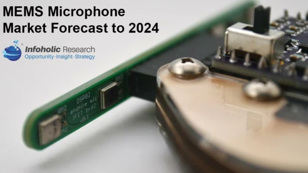
Global market for MEMS microphones • In 2006: $140 million, less than 12 companies • In 2011: $922 million, number of companies projected to double • Annual average growth rate of 45.7% • 1.1 billion units projected in 2013! • Applications of MEMS Microphones Motivation Graph from www.isupply.com • New idea • Proof of concept • Powerless signal generation • Offers alternative to piezoelectric and electret designs Market Projections and Statistics from www.mindbranch.com
Power Consumption in Common Alternative Technologies Piezoresisitive Microphone Mode of Power Consumption: Excitation voltage to measure resistance change. -Sheplak et al. Excitation Voltage: 10V Power Consumption: 0.7 mW -Arnold et al. Excitation Voltage: 3V Power Consumption: 15mW +/- 2.5mW http://www.acoustics.org/press/137th/pires1.jpg
Power Consumption in Common Alternative Technologies Piezoresisitive Microphone Mode of Power Consumption: Excitation voltage to measure resistance change. -Sheplak et al. Excitation Voltage: 10V Power Consumption: 0.7 mW -Arnold et al. Excitation Voltage: 3V Power Consumption: 15mW +/- 2.5mW http://www.acoustics.org/press/137th/pires1.jpg Condenser Microphone Mode of Power Consumption: Required bias voltage between plates -Pedersen et al. Bias Voltage: 4V Capacitance: 10.1 pF Power Consumption: 1.96mW http://www.totalvenue.com.au/articles/microphones/mic-condenser.gif
Power Consumption in Common Alternative Technologies Piezoelectric and Electret microphones No power required for signal generation Condenser Microphone Mode of Power Consumption: Required bias voltage between plates -Pedersen et al. Bias Voltage: 4V Capacitance: 10.1 pF Power Consumption: 1.96mW http://www.totalvenue.com.au/articles/microphones/mic-condenser.gif Piezoelectric Microphone Electret Microphone http://www.acoustics.org/press/137th/pirel1.jpg http://hyperphysics.phy-astr.gsu.edu/hbase/audio/imgaud/etret.gif
Design Components Basic design: • What? • A pre-fabricated surface-mount inductor (Coilcraft DO1607B, 6.8 mH) • Why? • Compensate for small flux with large coil • Why make it yourself (hard) when other people already do it? • Permanent magnet array considerations: • Magnet material? • Magnetization direction? • Magnet dimensions?
Ultimate design goal was to limit fabrication cost for industrial production • Electroplating • Low Cost • High Deposition Rate • Selectively pattern w/ photoresist Magnetic Material Selection Arnold et al.
Objective: • Fill the allotted space with a magnet arrangement which will produce maximum voltage • Voltage produced given by Faraday’s Law • Φ is the flux through the coil • Maximize the “flux density” i.e. field produced by the magnet • Approached this by asking some reasonable questions… Permanent Magnet Design
Question #1: In or out of plane? • Flux is ; take component perpendicular to A • Answer: Only out of plane will give desired flux change Permanent Magnet Design supplemental material on magnet simulations In-plane magnet Out-of-plane magnet
Question #2: Is there an optimal aspect ratio? Permanent Magnet Design • No magnet provides its full remanence unless in closed-circuit; instead, operates in second quadrant • Why? • Self-demagnetization slope = (B/H)max slope = B/H = f(N)? partial demagnetization (0 < N < 1), some remanence available slope = ∞: no demagnetization (N = 0), full remanence available • For open circuit application, ideal to design geometry to operate at (BH)max(Arnold 2009) slope = 0: complete demagnetization (N = 1), no remanence available BHmax = maximum energy available to do work (pushing electrons, for example)
Answer: Yes; optimal aspect ratio is 2.83 to operate at (BH)max(see supplemental slides for full calculation) • Question #3: plate or array? • Answer: only array is feasible • Array: magnets 10 um x 10 um x 28 (30 um max thickness) • Plate: single magnet 1.35 mm x 1.35 mm x 3.82 mm thick • Final result: • CoNiMnP • Array of 10 um x 10 um x 28 um • 10 um spacing (ease of fabrication) • Magnetized out of plane Permanent Magnet Design
Design Components Basic design: • Cantilever oscillation determines frequency response of microphone • Material? • Dimensions? • Optimized using anlytical simulation • Permanent magnet array considerations: • Magnet material? • Magnetization direction? • Magnet dimensions?
Objective:Develop an analytical model for the oscillatory behavior of the cantilever using the classic differential equation for a damped harmonic oscillator Modeling the Cantilever Analytically
Modeling the Cantilever Analytically Forcing Term In our application, the force is due to a pressure wave: For sound:
Modeling the Cantilever Analytically Effective Mass • The whole cantilever does not move at the same velocity • Effective mass = mass weighted by velocity relative to max • Integrals give: Our System Total Effective Mass: Plate case
Modeling the Cantilever Analytically Damping Constant Two contributions: 1. Mechanical • Slide Film: Damping generated by lateral motion of oscillator with respect to substrate (negligible with respect to other forms of damping) • Squeeze Film: Trapped air between oscillator and substrate exerts an opposing force Kim et al. 1999
Modeling the Cantilever Analytically Damping Constant Two contributions: 1. Mechanical 2. Electromagnetic • γm is dependent on • The magnetic field produced by the magnet • The current density, σ • this means… • Zero current = zero magnetic damping • Use device as a voltage source (~ infinite resistance) to minimize EM damping see supplemental slides for full calculation
Modeling the Cantilever Analytically ; Spring Constant Magnets are ~10x as thick as the cantilever, so k is ~1000x larger for magnets Springs in Series:
The quality factor describes the energy dissipated in an oscillatory system • Q > ½ = underdamped • Q < ½ = overdamped • For a mechanical system: • Signal to noise: ratio of signal amplitude to noise amplitude Quality Factor and Signal-to-Noise
Thermal Noise • Random thermal motion of atoms results in small displacements of cantilever Electrical Noise • Johnson • Flat frequency spectrum • Irreducible • Dependant on resistance • Shot • Random fluctuation in current • Charges act independently of each other
Cantilever motion modeled as a sinusoidal driven harmonic oscillator: Steady-state solution: Solving the Differential Equation
Looking for an even output across the range of human hearing (20 – 20,000 Hz) • In our case, we want a constant voltage amplitude • What part of the cantilever response affects the voltage output? • If the flux varies relatively slowly over z (and it does), the voltage depends primarily on the velocity • Optimize for flat velocity response What is an optimal frequency response? see supplemental slides for full derivation source: www.audio-technica.com
Optimizing Frequency Response • Range of human hearing: 20-20,000Hz • 3 types • ω0 at low end • ω0 at high end • ω0 within range • Damping allows for flat velocity • 2,500 Hz chosen because of high signal/noise ratio and flat response supplementary slides with S/N, A, and V
Optimizing Frequency Response • For ω0 = 2500Hz t = 3.06mm • For best response, L = W = 3mm • Gap height dictates damping constant • To flatten response, used gap height = 30 mm • Results in a damping of γ = 2.35x10⁻² kg/s
Final Parameters • Cantilever • L = W = 3mm • t = 3.06 um • keff= 0.468 N/m • meff = 7.5x10⁻⁸kg • γ = 2.35x10⁻² kg/s • Q = 7.93x10⁻³ • Magnet array • 9800 magnets • 140 magnets x 70 magnets • 10 μm x 10 μm x 28 μm
Output Voltage Voltage output from cantilever is: • z(t) = cantilever motion • N = equivalent # of coils = 10,453 • Need to show: • Flat response • Sufficient signal • Good translation of volume, frequency
Output Voltage (2) • Volume Replication • Frequency Replication
Grow 3 µm thick oxide and use E-beam deposition to deposit Cr and Au Use mask to pattern photoresist, then etch the Cr, Au, and oxide to create cantilever shape Pattern array for magnets in photoresist Electroplate magnets and magnetize Pattern photoresist to protect magnets and remove excess metal layers Fabrication
Crystalbond™ two wafers together on their patterned sides Pattern oxide on bottom, and then etch through Si Attach Coil Fabrication Cont.
Obstacles • ThickPhotoresist: • Under developed • Over developed • Skipped: • Magnet array protection during SiO2/Si etches • Gold removal • Si etching • Crystalbond™ adhesion incomplete • Doubled-sided etching/sliding wafers • Post-etch cantilever behavior • Etching away • Curling up Prototype Processing • Solutions • Patterning • SU-8 • Better aligner • Better masks (chrome on glass) • Si etching • DRIE (deep reactive ion etching) more pictures stress
4 cantilevers tested • Electrically connected to oscilloscope • Unsuccessfully looked for measurable signal produced by sound • What could have gone wrong • Solder: high resistance or incomplete circuit • Output too low • Deflection too small -> cantilevers too stiff -> Si layer • Magnets removed during handling • Gap height larger than planned Testing
Frequency response • Supply sound of constant volume, varied frequency (20-20,000 Hz), look for flatness of response • Amplitude response • Constant frequency, varied volume (30-80 dB? Depending on application), look for response proportional to pressure wave amplitude • Off-axis response • Measure signal produced for sound at angles to cantilever • Impulse response • Measures microphone response to brief sounds, necessary when observing brief or rapidly-occuring sounds Future Testing
Fabrication: • Safety for Workers • Waste in wet processing • Actual fabrication • Developing working process • Transition to mass production • Consumer: • Not enough magnetic material to be harmful • Protective packaging removes health risk • Disposal • Small waste concentrations Ethical Issues in Scaling Up
Prepare for the worst! Nothing goes as exactly planned Problem solving skills Teamwork is necessary for success Practicality of microprocessing Sometimes the 3rd time is still not the charm Higher understanding of spring-mass system Utilize unfamiliar software packages What Have We Learned?
Acknowledgements • Dr. Phaneuf • Dr. Briber • Dr. Wuttig • Dr. Ankem • John Abrahams • Tom Loughran • Don Devoe • Coilcraft • Fineline Imaging
Demonstrate a functional MEMS magnetic sensor Model mechanical behavior of millimeter scale cantilever supporting a substantial mass Investigate magnetic induction at a small scale Optimize magnetic properties of small magnet arrays Apply electroplating to large aspect ratios Intellectual Merit
1st Generation: Drumhead Oscillator Bulk micromachining Surface micromachining Planar Abandoned due to insufficient deflection under acoustic loading. 2nd Generation: Air-bridge/Cantilever Oscillator Single Magnet Dual Magnet Micro-magnet Array Design Evolution
Bulk Micromachining Si Primary Challenge: Electroplating the magnet beneath the diaphragm Attributes for Prototype: Releasing the diaphragm is a simple process
Surface Micromachining SiO2 Primary Challenge: Fabricating the diaphragm and acoustic cavity above the magnet Attributes for Prototype: Electroplating magnet can occur early in the process flow
Planar Primary Challenge: Interfacial stresses between magnet, adhesion layer, and diaphragm may cause delamination under acoustic loading. Attributes for Prototype: Arrays of smaller magnets may reduce interfacial stresses
Single Magnet Cantilever Coil Magnet SiO2 Si Not drawn to scale Primary Challenge: Positioning the magnet to maximize the flux change under acoustic loading. Attributes for Prototype: Electroplating the magnet on the cantilever simplifies the fabrication process
Dual-Magnet with Coil Cantilever Primary Challenge: Flux change is not directed through coil (no EM induction) Attributes for Prototype: Magnetic field behavior of multiple magnets
Prototype Current Design: -SiO2 cantilever -Different Magnet Spacing Arrays of magnets with spacing of 0 μm (monolithic plate), 10, 20, 30, and 40 μm -Back etched acoustic cavity -Prefabricated surface inductor (6800 μH Coilcraft)
Diaphragm • Cantilever Diaphragm vs. Cantilever