Download
1 / 18
180 likes | 206 Views
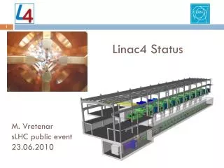
Linac4 Overview. M. Vretenar, SLHC Meeting, 26.2.2009. Motivations Layout Main parameters Schedule Status. The upgrade of the LHC Injectors.

E N D
Linac4 Overview M. Vretenar, SLHC Meeting, 26.2.2009 • Motivations • Layout • Main parameters • Schedule • Status
The upgrade of the LHC Injectors Motivations: progressively increase the LHC luminosity, increase reliability, simplify operation, reduce radiation, open to new physics applications. Phase 1: Approved 06/2007, started 2008 Phase 2: Design approved 06/2007 (LP)SPL: (Low Power)Superconducting Proton Linac (4-5 GeV) PS2: High Energy PS (~ 5 to 50 GeV – 0.3 Hz) SPS+: Superconducting SPS (50 to1000 GeV) SLHC: “Superluminosity” LHC (up to 1035 cm-2s-1) DLHC: “Double energy” LHC (1 to ~14 TeV)
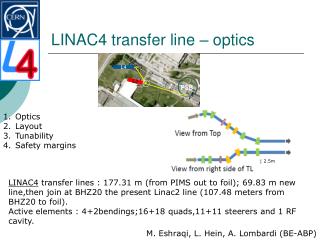
Linac4 on the CERN site PS Linac4 will be built in an area between the PS complex and the IT building where used to be the “Mount Citron”. Position and orientation allow future extension to the SPL. A transfer line from the Linac4 tunnel connects to the present Linac2-PSB line. PSB PS2 - SPS Transfer line Future SPL Present 50 MeV Linac2 Linac4
Linac4 civil engineering Equipment building ground level Linac4 tunnel Linac4-Linac2 transfer line Low-energy injector Access building Pre-integration May – October 2007 Tendering drawings November 2007 – April 2008 Tendering May 2008, Contract to FC September 2008. Civil Engineering Works October 2008- November 2010.
Civil engineering is progressing 27.11.2008 15.12.2008 23.02.2009
Linac4 - motivations • Linac4 is a normal-conducting H− linac at 160 MeV energy that will replace Linac2 as injector to the PSB and can be lately extended to the SPL. Linac4 because the 4th linac to be built at CERN (Linac3 is the heavy-ion linac). • 160 MeV energy gives a factor 2 in bg2 with respect to the present 50 MeV Linac2 factor 2 increase in bunch density in the PSB easier production of LHC beam, margin to reach ultimate luminosity.
Linac4 Parameters H− particles + higher injection energy (160/50 MeV, factor 2 in bg2) same tune shift in PSB with twice the intensity. Ion species H− Output Energy 160 MeV Bunch Frequency 352.2 MHz Max. Rep. Rate 2 Hz Max. Beam Pulse Length 1.2 ms Max. Beam Duty Cycle 0.24 % Chopper Beam-on Factor 65 % Chopping scheme: 222 transmitted /133 empty buckets Source current 80 mA RFQ output current 70 mA Linac pulse current 40 mA N. particles per pulse 1.0 × 10¹⁴ Transverse emittance 0.4 p mm mrad Max. rep. rate for accelerating structures 50 Hz Re-use 352 MHz LEP RF components: klystrons, waveguides, circulators. Chopping at low energy to reduce beam loss at PSB. • Structures and klystrons dimensioned for 50 Hz • Power supplies and electronics dimensioned for 2 Hz, 1.2 ms pulse.
Linac4: 3 modes of operation Linac4 is designed to operate in 3 different modes: Injector to PS Booster(2013-2017?): 1.1 Hz, 40 mA, 400 ms. Injector to Low Power-SPL(2018- ?): 2 Hz, 20 mA, 1.2 ms only minor upgrades Injector to High Power-SPL(>2020 ?): 50 Hz, 40 mA, 1.2 ms max. important upgrade (RF modulators, power supplies, cooling, etc.) Main consequences on the design: Shielding dimensioned for the SPL high beam power operation (1 W/m beam loss). Accelerating structures and klystrons dimensioned for high duty operation. Power supplies, electronics and infrastructure (water, electricity) dimensioned only for low beam power operation (PSB, LP-SPL). Space provided at the end of the linac for the connection to the SPL
Linac4 challenges • First challenge of Linac4 is RELIABILITY: must operate ~6000 hours/year with a fault rate comparable to Linac2, ~1.5% of scheduled beam time. • Control of transverse and longitudinal EMITTANCE GROWTH is of paramount importance for clean PSB and SPL injection. • Careful LOSS CONTROL to prepare for the SPL mode of operation uncontrolled beam loss <1 W/m in SPL mode <0.1 W/m in PSB injection mode (at 160 MeV, 1.5*10-5/m loss rate). • Keep the COST of the machine within what is acceptable in the critical post-LHC period.
Linac4 Layout 45keV 3MeV 3MeV 50MeV 102MeV 160MeV H- RFQ CHOPPER DTL CCDTL PIMS Drift Tube Linac 352 MHz 18.7 m 3 tanks 3 klystrons 4 MW 111 PMQs Cell-Coupled Drift Tube Linac 352 MHz 25 m 21 tanks 7 klystrons 6.5 MW 21 EMQuads Pi-Mode Structure 352 MHz 22 m 12 tanks 8 klystrons ~12 MW 12 EMQuads RF volume source (DESY type) Radio Frequency Quadrupole 352 MHz 3 m 1 Klystron 540 kW Chopper Line 352 MHz 3.6 m 11 EMquad 3 cavities Total Linac4: 80 m, 18 klystrons 4 different structures, (RFQ, DTL, CCDTL, PIMS) RF Duty cycle: 0.1% phase 1 (Linac4) 3-4% phase 3 (HP-SPL) Ion current: 40 mA (avg. in pulse), 65 mA (bunch)
Linac4 accelerating structures DTL, 3 – 50 MeV CCDTL, 50 – 100 MeV PIMS, 100 – 160 MeV Cell-Coupled Drift Tube Linac (7 modules) Modules of 3 DTL-type cavities (2 drift tubes), connected by coupling cells. Prototypes built and tested, construction starts in 2009 Drift Tube Linac (3 tanks) Prototype built, under testing. Costruction starts in 2009 7-cell cavities in p-mode (12 cavities) Prototype in construction
The 3 MeV Test Stand RFQ source chopper line • In construction in the South Hall extension. • - H- source (2008) • LEBT (2008-09) • RFQ (February 2010) • Chopper line (2008) • Diagnostics line (2010) • Infrastructure (1 LEP Klystron, pulsed modulator, etc.) - ready • In the front end are concentrated some of the most challenging technologies in linacs, and this is where the beam quality is generated. Early understanding and optimisation of front-end is fundamental for a linac project. diagnostics line klystron modulator
3 MeV Test Stand – 02/2009 Chopper line assembled LEP-type klystron and prototype modulator under test
Linac4 Master Plan • End CE works: December 2010 • Installation: 2011 • Linac commissioning: 2012 • Modifications PSB: shut-down 2012/13 (7.5 months), to be confirmed. • Beam from PSB: June 2013
45 keV 3 MeV 50 MeV 90 MeV 160 MeV H - PIMS CCDTL RFQ DTL transfer line to PSB chopper line LEBT source 352 MHz 704 MHz 80 m Linac4 R&D collaborations (2004-2008) INDIA: klystron power supplies, waveguides SAUDI ARABIA: RF prototypes PAKISTAN vacuum chambers, supports DESY IPHI HIPPI ISTC # 2888 & 2889 ISTC # 2875 Network of collaborations for the R&D phase, via EU-FP6, CERN-CEA/IN2P3, ISTC (CERN-Russia), CERN-India and CERN-Pakistan agreements. International participations to the construction of Linac4 under definition: Signed or being signed: Russia (CCDTL), France (modulators, etc.), Pakistan (transfer line) In preparation: Saudi Arabia (DTL tanks), Poland (PIMS), India (supports, waveguides, couplers, etc.), USA (diagnostics).
FP6 (CARE-HIPPI) for Linac4 HIPPI = “High Intensity Pulsed Proton Injectors”Joint Research Activity in CARE, active from 2004 to 2008, has given an essential contribution to the Linac4 R&D: • Development and prototyping of the Linac4 accelerating structures. • Design and construction of the chopper structure and of the chopper line. • Development of the beam optics, benchmarking of codes. • Development of specific diagnostics. • In contact (exchange of information and expertise) with the other EU labs and with the support of an External Advisory Committee.
Linac4 Status (02/2009) • Civil Engineering works started 22.10.2008, delivery of building end 2010. • Preliminary Safety File submitted to CERN Safety Commission in June 2008. Building approved. • Ion source almost completed, first beam tests expected soon. • 3 MeV Test Stand infrastructure completed. • RFQ in construction, ready by end of 2010. • Prototype modulator tested with LEP klystron in pulsed mode. • Chopper line built and assembled. • Prototypes of accelerating structures tested (CCDTL), being tested (DTL), starting construction (PIMS). Material being ordered, construction of DTL and CCDTL will start in 2009. • Started preparation for large contracts (klystrons, modulators, magnets,…). • Workpackages finalises, complete project in EVM, project baseline being frozen.