Download
1 / 20
200 likes | 382 Views
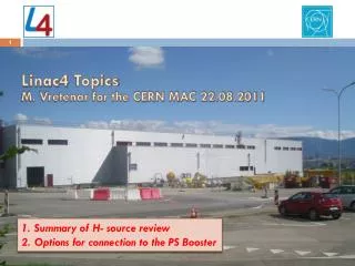
Linac4 Status. M. Vretenar, 30.10.2008. Linac4 on the CERN site. Linac4 will be built at the place of the “Mount Citron”, a small hill made in the 50’s from the excavation materials of the PS. Position and orientation allow a future extension to the SPL. PS. PSB. PS2 - SPS.

E N D
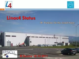
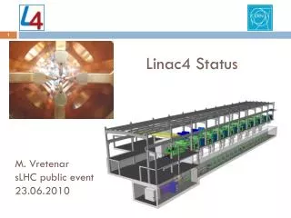
Linac4 Status M. Vretenar, 30.10.2008
Linac4 on the CERN site Linac4 will be built at the place of the “Mount Citron”, a small hill made in the 50’s from the excavation materials of the PS. Position and orientation allow a future extension to the SPL. PS PSB PS2 - SPS Transfer line to Linac2 Future SPL Linac4
Linac4 Groundbreaking 16 October 2008, Linac4 Groundbreaking by CERN Director, R. Aymar
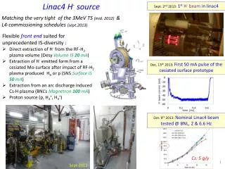
Linac4 – Milestones • June 2007: approval of the project by the CERN Council. • January 2008: official project start (budget available). • May 2007: Defined linac position and type of tunnel, start pre-integration. • November 2007 – April 2008: Preparation of CE tendering drawings. • May 2008: CE Tendering • September 2008: Contract attribution. • 22 October 2008: Start Civil Engineering works. • December 2010: Tunnel and Hall delivery. • December 2011: Move Front-End to the linac tunnel. • January 2012: Start installation of DTL, CCDTL, PIMS. • February 2012: Front-end re-commissioning. • May-October 2012: DTL, CCDTL, PIMS commissioning. • November 2012: Transfer line commissioning, start PS Booster modifications. • March 2013: Start of PS Booster commissioning with Linac4 beam. • June 15th, 2013: Start physics run with Linac4 beam.
Linac4 Parameters H− particles + higher injection energy (160/50 MeV, factor 2 in bg2) same tune shift in PSB with twice the intensity. Ion species H− Output Energy 160 MeV Bunch Frequency 352.2 MHz Max. Rep. Rate 2 Hz Max. Beam Pulse Length 1.2 ms Max. Beam Duty Cycle 0.24 % Chopper Beam-on Factor 65 % Chopping scheme: 222 transmitted /133 empty buckets Source current 80 mA RFQ output current 70 mA Linac pulse current 40 mA N. particles per pulse 1.0 × 10¹⁴ Transverse emittance 0.4 p mm mrad Max. rep. rate for accelerating structures 50 Hz Re-use 352 MHz LEP RF components: klystrons, waveguides, circulators. Chopping at low energy to reduce beam loss at PSB. • Structures and klystrons dimensioned for 50 Hz • Power supplies and electronics dimensioned for 2 Hz, 1.2 ms pulse.
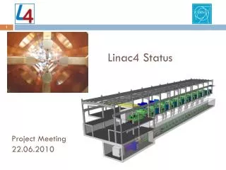
Linac4 Layout 45keV 3MeV 3MeV 50MeV 94MeV 160MeV H- RFQ CHOPPER DTL CCDTL PIMS Drift Tube Linac 352 MHz 18.7 m 3 tanks 3 klystrons 4 MW 111 PMQs Cell-Coupled Drift Tube Linac 352 MHz 25 m 21 tanks 7 klystrons 6.5 MW 21 EMQuads Pi-Mode Structure 352 MHz 22 m 12 tanks 8 klystrons ~12 MW 12 EMQuads RF volume source Radio Frequency Quadrupole (IPHI) 352 MHz 6 m 1 Klystron 1 MW Chopper 352 MHz 3.6 m 11 EMquad 3 cavities Total Linac4: 80 m, 18 klystrons Beam Duty cycle: 0.24% phase 1 (LP-SPL) <6% phase 2 (HP-SPL) 4 different structures, (RFQ, DTL, CCDTL, PIMS) Ion current: 40 mA (avg. in pulse), 65 mA (bunch)
The 3 MeV Test Stand RFQ source chopper line • In construction in the South Hall extension. • - H- source (2008) • LEBT (2008-09) • RFQ (February 2010) • Chopper line (2008) • Diagnostics line (2010) • Infrastructure (1 LEP Klystron, pulsed modulator, etc.) - ready • In the front end are concentrated some of the most challenging technologies in linacs, and this is where the beam quality is generated. Early understanding and optimisation of front-end is fundamental for a linac project. diagnostics line klystron modulator
The RFQ • Original idea: • Use the RFQ being built in France for the IPHI project, after the tests at Saclay. • However, • This RFQ is now late by >2 years. • Problems (microleaks) on 1st segment. • The design parameters (95 kV injection energy, length 6 m) are not optimum for Linac4. • Conclusion: • Decision (summer 07) to build a new CERN RFQ optimised for Linac4: • 45 kV injection, 3 m length. • CERN+CEA beam dynamics and RF design, • CERN mechanical design, based on INFN and CEA designs (TRASCO and IPHI). • c. Construction and brazing in the CERN Workshops.
Linac4 accelerating structures Linac4 accelerates H- ions up to 160 MeV energy: • in about 80 m length • using 4 different accelerating structures, all at 352 MHz • the Radio-Frequency power is produced by 19 klystrons • focusing of the beam is provided by 111 Permanent Magnet Quadrupoles and 33 Electromagnetic Quadrupoles PIMS A 70 m long transfer line connects to the existing line Linac2 - PS Booster
Linac4 accelerating structures DTL CCDTL PIMS 7-cell cavities in p-mode. With respect to the SCL, the PIMS : • has 5 times less cells (less machining time and cost). • needs about the same quantity of copper. • allows a simpler tuning (7 cells instead of >100, dummy tuners). • allows standardisation of the Linac4 frequency to 352 MHz. • has only about 12% less shunt impedance. Modules of 3 SDTL-type cavities with 2 drift tubes, coupled by 2 coupling cells. • Easy access and alignment of electromagnetic quadrupoles. • Relaxed tolerances on drift tube alignment. Conventional DTL structure with: • PMQs in vacuum inside drift tube. • no drift tube adjustment after installation.
Accelerating structures: gradients, peak fields, margins on RF power Optimum gradient in the different structures determined by cost considerations. For calculations, structure cost 180-250 kCHF/m, RF cost 450-650 kCHF/W Maximum surface field limited to 1.8 Kilpatrick (considered as safe enough for a pulsed machine) Maximum cavity power (copper, beam) 1 MW for klystrons (LEP) giving 1.2-1.3 MW (~20% margin for regulation and losses in waveguides) 20% margin from theoretical Q-value for additional losses in cavities
The Linac4 RF system Linac4 will reuse the stock of high-power klystrons coming from the old LEP accelerator: Initial configuration: 13 klystrons 1.3 MW, 6 klystrons 2.5 MW, 3 modulators 1.3 MW, 11 modulators 2.5 MW Final configuration (at the end of the stock of LEP klystrons): 3 klystrons 1.3 MW, 11 klystrons 2.5 MW, 3 modulators 1.3 MW, 11 modulators 2.5 MW
Linac4 civil engineering Equipment building ground level Linac4 tunnel Linac4-Linac2 transfer line Low-energy injector Access building Pre-integration May – October 2007 Tendering drawings November 2007 – April 2008 Tendering May 2008, Contract to FC September 2008.
Linac4 Work Breakdown Structure Total of 30 Workpackages
Linac4 Master Plan • End CE works: December 2010 • Installation: 2011 • Linac commissioning: 2012 • Modifications PSB: shut-down 2012/13 (7.5 months) • Beam from PSB: 15.6.2013 White Paper
Linac4 Budget Does not include: chopper line (built in HIPPI) 13 klystrons + waveguides from LEP Budget is covered by White Paper funding (55 MCHF) CERN budget for 2011-12 (38 MCHF)
Linac4 Status (10/2008) • Civil Engineering works started 22.10.2008, delivery of building end 2010. • Safety File submitted to CERN Safety Commission, June 2008. Building approved. • Ion source almost completed, first beam tests end 2008. • 3 MeV Test Stand infrastructure completed. • Prototype modulator tested with LEP klystron in pulsed mode. • Prototypes of accelerating structures tested (CCDTL), in construction (DTL), in final design stage (PIMS). Material being ordered, construction of DTL and CCDTL will start in 2009. • Started preparation for large contracts (klystrons, modulators, magnets,…). • Detailed descriptions of Workpackages in preparation, project baseline will be frozen at end 2008. • Advanced negotiations for in-kind contributions with France, Russia (via the ISTC Organisation), Poland, Spain (via ESS-Bilbao), India, Pakistan, Saudi Arabia.