LINAC4 emittance measurements
190 likes | 455 Views
LINAC4 emittance measurements. BI Day Divonne, 24 th November. Outline. Introduction LINAC4 emittance measurement Source and LEBT commissioning Slit design for 3 and 12 MeV commissioning phase Summary and outlook. Slit & Grid system. Scanning slit position For each slit position

LINAC4 emittance measurements
E N D
Presentation Transcript
LINAC4 emittance measurements BI Day Divonne, 24th November B.Cheymol, E. Bravin, D. Gerard, U. Raich, F. Roncarolo BE/BI
Outline • Introduction • LINAC4 emittance measurement • Source and LEBT commissioning • Slit design for 3 and 12 MeV commissioning phase • Summary and outlook B.Cheymol, E. Bravin, D. Gerard, U. Raich, F. Roncarolo BE/BI
Slit & Grid system • Scanning slit position • For each slit position • profile monitor gives beamlet divergence • Transverse phase space reconstruction B.Cheymol, E. Bravin, D. Gerard, U. Raich, F. Roncarolo BE/BI
Emittance measurement in LINAC4 • Slit and grid will be used during commissioning phase • In the low energy section (45 keV) • At 3 (RFQ and Chopper line) and 12 MeV (1st DTL Tank) • Determination of source beam emittance • Determination of matching parameters • Study of the accelerator optics • Issue of the system: • @ 45 KeV • Large beam sizes and divergence • Space charge forces • Background from beam dump • @ 3 and 12 MeV • Thermal load on the slit B.Cheymol, E. Bravin, D. Gerard, U. Raich, F. Roncarolo BE/BI
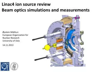
Low energy emittance meter B.Cheymol, E. Bravin, D. Gerard, U. Raich, F. Roncarolo BE/BI
Emittance-Meter: background reduction • Emittance measurement can be perturbed by SE from beam dump positioned downstream the emittance meter • Rings can be polarized to reduce number of particles travelling backward • Dump can be used as a Faraday cup Faraday’s cup plate B.Cheymol, E. Bravin, D. Gerard, U. Raich, F. Roncarolo BE/BI
Emittance-Meter: background reduction simulations + 500 V Configuration considered initially: VP1>0 , VP2<0 Electrons trajectories as simulated by CST Microwave Studio Faraday’s Cup P2 P1 - 500 V + 1200 V Configuration proposed after simulations: VP1,VP2, VCUP > 0 • minimizes perturbation due to FC and P1 electrons • biasing the FC forbids charge measurements at the same time as emittance measurements
Emittance-Meter: bias rings setup with beam During Beam charge measurement at the Faraday’s Cup (H- 35 keV) -Need VP2 < 0 to retain secondary electrons that would escape the CUP During Emittance Measurement -all biases > 0 clearly optimizes the wire signal All well in agreement with MWS simulations B.Cheymol, E. Bravin, D. Gerard, U. Raich, F. Roncarolo BE/BI
Source and LEBT commissioning B.Cheymol, E. Bravin, D. Gerard, U. Raich, F. Roncarolo BE/BI
LEBT Commissioning Stages 1 Completed with 35 keV H-and 45 keV Protons 2 Completed with 45 keV Protons 3 4 • Stage 4 completed • Now: will re-check stage 1 while re-arranging LEBT to host RFQ (beginning of 2012) B.Cheymol, E. Bravin, D. Gerard, U. Raich, F. Roncarolo BE/BI
Emittance-Meter Measurement Example (I) Emittance-meter measurement after 1st solenoid X’ 45 keV Proton source: different charge states produced by the source are focused differently as they pass through the solenoid 80% of protons H3+ H0 H2+ Protons X B.Cheymol, E. Bravin, D. Gerard, U. Raich, F. Roncarolo BE/BI
Emittance-Meter Measurement Example (II) Transverse distribution vs Source RF power Profiles extracted from Emittance Measurements (phase space projection on HOR axis) B.Cheymol, E. Bravin, D. Gerard, U. Raich, F. Roncarolo BE/BI
Profile measurements with emittance meter Profile Measurement performed after the second solenoid by measuring the FC current while scanning the slit position This particular measurement proved • Source reproducibility (red and blue measurements taken in different days) • beam-solenoid misalignment (beam centroid depends on Solenoid current) B.Cheymol, E. Bravin, D. Gerard, U. Raich, F. Roncarolo BE/BI
Slit design for 3 and 12 MeV commissioning phase B.Cheymol, E. Bravin, D. Gerard, U. Raich, F. Roncarolo BE/BI
Thermal load at 3 and 12 MeV • Commissioning will be done with a 65 mA and 100 μs beam (4 x10¹³ particles per pulse) • @ 3MeV: • Power (over pulse) =>0.31 MW.cm-2 • @ 12 MeV: • Power (over pulse) =>7.56 MW.cm-2 x • The blade is tilted to spread the energy deposition on a larger surface. • Graphite has been chosen for thermal properties z θ B.Cheymol, E. Bravin, D. Gerard, U. Raich, F. Roncarolo BE/BI
Slit geometry Maximum in temperature for the three commissioning stages, as estimated by analytical model (SRIM) and numerical simulations (FLUKA) when considering a 65 mA, 100 μs pulse. Energy deposition along the z axis for three slit angles at 3 MeV(MEBT), in case of a Graphite slit. Even with 15°, thermal load is too high for DTL case. Decided to move the slit 1 m downstream beam sizes increase by a factor 1.5 Temperature drops to 1520 K B.Cheymol, E. Bravin, D. Gerard, U. Raich, F. Roncarolo BE/BI
High energy Slit design • Graphite plates clamped on a copper block • Slit aperture adjustable at the assembly (100 or 200 μm) • Slit thickness equal to 1 mm. B.Cheymol, E. Bravin, D. Gerard, U. Raich, F. Roncarolo BE/BI
Status • Mechanical design Completed (done by CERN design office) • Slit tank is under assembly (followed by D. Gerard) • Emittance meter will be ready for RFQ commissioning (March-April 2012) B.Cheymol, E. Bravin, D. Gerard, U. Raich, F. Roncarolo BE/BI
Summary and outlook • Source and LEBT test stand operated for two years • Commissioning stages with 45 keV proton source completed • Beam parameter and optics has been characterized • Faraday’s cups to validate transmission • Emittance meter to validate matching to nominal optics • Spectrometer SEM grid to measure energy spread • RFQ and Chopper commissioning with proton beam in 2012 • Commissioning of the new H- source and LEBT (with larger aperture) B.Cheymol, E. Bravin, D. Gerard, U. Raich, F. Roncarolo BE/BI