Download
1 / 17
180 likes | 369 Views
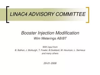
LINAC4 ADVISORY COMMITTEE. Booster Injection Modification Wim Weterings AB/BT With input from B. Balhan, J. Borburgh, T. Fowler, B.Goddard, M. Hourican, L. Sermeus and many others 29-01-2008. Talk Overview. Booster Injection Principle Beam Distribution LINAC4 Pulse Structure

E N D
LINAC4 ADVISORY COMMITTEE Booster Injection Modification Wim Weterings AB/BT With input from B. Balhan, J. Borburgh, T. Fowler, B.Goddard, M. Hourican, L. Sermeus and many others 29-01-2008
Talk Overview • Booster Injection Principle • Beam Distribution • LINAC4 Pulse Structure • Beam Separation • H- charge-exchange Injection System • Principle • Foil Heating • Layout and Available Space • Required Modifications • Main Design Parameters • Present Status • Conclusion W. Weterings - LINAC4 Advisory Committee
Booster Injection Principle Vertical Septum BI.SMV & BI.BVT Beam slices are further deflected by the BI.SMV septa into the BI.BVT vertical dipole apertures to achieve the required booster beam level separation of 360 mm between each ring Proton Distributor BI.DIS system of pulsed magnets, which kick slices of the beam to different vertical positions at the vertical septum BI.SMV H- Charge-Exchange Injection System 160 MeV H- beam from LINAC4 is injected through a graphite stripping foil to convert ~98% of the beam to protons, using two independent closed orbit bump systems W. Weterings - LINAC4 Advisory Committee
Booster Injection Principle 4 = 360 mm BI.QNO30 BI.QNO40 BI.DVT40 BI.DVT30 3 = 0 mm 2 = -360 mm BI.DIS BI.SMV BI.BVT PSB 1 = -720 mm W. Weterings - LINAC4 Advisory Committee
Booster Injection Principle Beam Distribution Proton Distributor BI.DIS • LINAC4 beam enters the BI.DIS with a ~5.2 mm vertical offset. • The BI.DIS system, in combination with BI.DVT40, kicks slices of the beam into the different vertical septa BI.SMV. • a ~3.5 mrad deflection producing a vertical beam separation of 35 mm at the the BI.SMV. • In case of BI.DIS failure, the full beam is deflected by BI.DVT40 into an absorber block (head-dump). W. Weterings - LINAC4 Advisory Committee
DIS 0 DIS 1 DIS 2 DIS 3 DIS 4 DIS 0 DIS 1 DIS 2 DIS 3 DIS 4 HeadDump TailDump 65 to 100µs 1µs 3 ~ 5µs 1µs Ring 4 Ring 3 Ring 2 Ring 1 Booster Injection Principle LINAC4 Pulse Structure Proton Distributor BI.DIS • 4 individual LINAC4 pulses, typically 65~100µs long with 1µs gap for BI.DIS rise-time. • Fixed BI.DIS pulse lengths, but different for each magnet. • Timing to be adjusted according to required number of injection turns from pulse to pulse. Example: Operation 65~100 injected turns/ ring Example: Pilot Beams 3~5 injected turns/ ring W. Weterings - LINAC4 Advisory Committee
Booster Injection Principle Beam Separation Magnetic Septa BI.SMV • The rising edge of the LINAC4 pulse is deflected to a absorber block (head dump). • BI.SMV septa deflect the beam vertically into apertures of 3 separate BI.BVT vertical dipole magnets to achieve the required PSB beam level separation of 360 mm between each ring. • Beam designated for ring 3 will see no magnetic field and passes between SMV2 and SMV3. • The falling edge of the LINAC4 pulse is deflected to a second absorber block (tail dump). W. Weterings - LINAC4 Advisory Committee
H- Injection System Principle Booster Injection Region • Two independent closed orbit bump systems: • Injection Chicane, 4 pulsed dipole magnets (BS), located in the injection region, giving 60 mm beam offset during the injection process. • Painting Bump, 4 horizontal kickers (KSW), located outside the injection region, giving 27 mm closed orbit bump with falling amplitude over the injection process for transverse phase space painting. • BS1 must act as septum. • BS4 should accommodate internal Dump. • Stripping efficiency of ~98% expected. W. Weterings - LINAC4 Advisory Committee
H- Injection System Foil Heating Booster Injection Region Temperature [K] of a 2 μm thick,400 μg.cm-2 graphite foil at the end of the injection of 7 CNGS pulses. Peak foil temperature over 7 CNGS cycles. W. Weterings - LINAC4 Advisory Committee
Layout and Available Space Side View Top View W. Weterings - LINAC4 Advisory Committee
Layout and Available Space W. Weterings - LINAC4 Advisory Committee
Required Modifications Relocate modified KSW1L1 magnet to PSB period 16, build new pulse generator. Remove obsolete BI.DIS Pb ~0.36 Tm required from BI.BVT for ~187mrad@160MeV Modify BI.DIS for4.3 mrad @ 160 MeV New BI.SMV,4 mm thick septum and 70 mm horizontal aperture for ~180 mrad @ 160 MeV.New pulse generator. • Rebuild the 2.654 m injection region of each of the 4 PSB rings: • 4 new BS magnets, • Foil holder and handler, • Dump for unstripped H0/H-, • Beam Instrumentation. Performance increase of 1.9 in ∫B•dl of BI.DVT30, BI.QNO30, BI.QNO40, BI.DVT40. W. Weterings - LINAC4 Advisory Committee
Required Modifications Relocate modified KSW1L1 magnet to PSB period 16, build new pulse generator. Remove obsolete BI.DIS Pb ~0.36 Tm required from BI.BVT for ~187mrad@160MeV Modify BI.DIS for4.3 mrad @ 160 MeV New BI.SMV,4 mm thick septum and 70 mm horizontal aperture for ~180 mrad @ 160 MeV.New pulse generator. • Rebuild the 2.654 m injection region of each of the 4 PSB rings: • 4 new BS magnets, • Foil holder and handler, • Dump for unstripped H0/H-, • Beam Instrumentation. Performance increase of 1.9 in ∫B•dl of BI.DVT30, BI.QNO30, BI.QNO40, BI.DVT40. W. Weterings - LINAC4 Advisory Committee
Main Design Parameters W. Weterings - LINAC4 Advisory Committee
Present Status • BI.DIS - Design of new vacuum vessel well advanced. - Existing magnet tested for 160 MeV operation. - Specification for ferrite cores in preparation. - Coil design under study.- Challenge: Operation at 30 kV. • BI.SMV - Magnet parameters have been defined. - Design & prototyping planned to start mid 2008.- Challenge: Build curved, high induction, septum magnet to operate under vacuum. • KSW - Studies of moving 1L1 to period 16 ongoing. - If moved, build outside vacuum magnets.- Challenge: Beam optics compatibility. W. Weterings - LINAC4 Advisory Committee
Present Status • BS - Basic prototype has been tested to validate OPERA™ simulations. - 3D finite element transient field analysis ongoing. - Aperture and parameter optimization studies.- Challenge: Build cost-effective fast pulsed bumper system. • Foil Unit - Nuclear foil physics effects are being studied.- Challenge: Foil changing unit in limited space. • Ho/H- Dump & Head/Tail Dumps - Thermo-mechanical studies being prepared. - Challenge: Robust dumps in limited space. Overall Challenge: Injection system for 4 Superimposed PSB rings W. Weterings - LINAC4 Advisory Committee
Conclusions • In order to distribute and inject the 160 MeV beam from LINAC4 into the four rings of the PSB, new distributor magnets and magnetic septa with a performance increase of 1.9 in ∫B·dl need to be built. • The pulse structure from LINAC4 will consist of 4 individual pulses, typically 65-100 μs long. The distributor pulse length will be fixed, but different for each magnet. • A completely new H- charge-exchange injection needs to be built comprising four injection dipole magnets, a stripping foil unit, an internal beam dump, and suitable instrumentation. W. Weterings - LINAC4 Advisory Committee