Download
1 / 20
200 likes | 239 Views
This model analyzes the performance of Darrieus wind turbines by dividing the rotor into multiple stream tubes. It provides a more realistic distribution of blade forces and can account for wind shear effects.

E N D
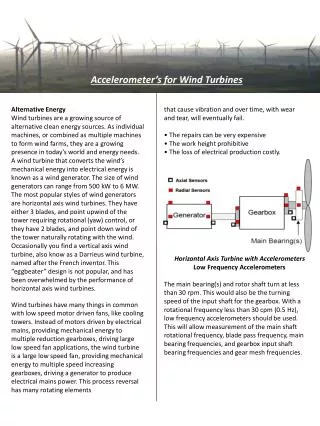
Double-multiple Stream Tube Model for Darrieus Wind Turbines P M V Subbarao Professor Mechanical Engineering Department Flow Thru VAWT is not Axi-symmetric.....
Simple & Sophisticated Model • A somewhat more sophisticated model than the single stream tube model is one in which a series of stream tubes are assumed to pass through the rotor. • The same basic principles which were applied to each of the multiple stream tubes. • The multiple stream tube model gives rise to a velocity distribution through the rotor which is a function of the two spatial coordinates perpendicular to the stream wise direction. • The multiple stream tube model does predict overall performance very well. • This model yields a more realistic distribution of blade forces, and can easily be modified to include wind shear effects.
Simplified Geometry of stream tubes in the plane of rotation • The swept area is discretized into a mesh by dividing the straight blades into segments and separating the incident wind into independent stream tubes. • Figure illustrates the independent straight stream tubes for a choice of 16 azimuthal positions
The Double Multiple Stream tube Analysis • The Double Multiple Stream tube (DMST) Method recognizes the difference between the upwind and downwind passes of each blade by dividing each stream tube into an upwind half and a downwind half . • The turbine’s interaction with the wind in the upwind and downwind passes of the blades is accounted separately. • The assumption is made that the wake from the upwind pass is fully expanded and the ultimate wake velocity has been reached before the interaction with the blades in the downwind pass. • The downwind blades therefore see a reduced ‘free-stream’ velocity. • This approach more accurately represents the variation in flow through the VAW turbine.
Description of Double Multi Stream Tube Model • Each stream tube in the DMST model intersects the airfoil path twice. • Once on the upwind pass, and again on the downwind pass. • At these intersections, the turbine replaced by a tandem pair of actuator discs, upon which the flow may exert force. i Betz Model : The induced velocity (Vau) on the upstream wind will be the average of the air velocity at far upstream (V∞) and the air velocity at downstream equilibrium (Ve). Vau Vad Ve Vw
Double Multi Stream Tube Model i Vau Vad Ve Vw Fluid Dynamic Model : The induced velocity (Vau) on the upstream wind is V∞(1-a) and the air velocity at downstream equilibrium is Ve= V∞(1-b)
Local Instantaneous Forces i Vad Ve Vw i Vau
Local Instantaneous Relative velocity diagrams for ith Stream Tube Vau VRu Vau Vau The upstream relative velocity component of ith Stream tube at jth height (Vru,ij)
Local Instantaneous diagrams for ith Stream Tube Vau VRu Vau Vau Normalized relative velocity
Local Instantaneous Torque per Blade (Upstream) Vau VRu Vau Vau The local instantaneous Tangential force (dFt,ij) on one single airfoil at certain i is The local instantaneous Torque (dij) on one single airfoil at certain iis
The Local Average Tangential Force & Torque • The time averaged tangential force acting in a stream tube by “B” blades per revolution can be expressed as • The time averaged torque acting in a stream tube by “B” blades per revolution can be expressed as
Double-multiple Stream Tube Model for A VWAT • The total torque developed by a VWAT • The total power developed by a VWAT
R
Periodic Kinematics of VAWT Blade V(1-a) VR V(1-a) r r VR Ve(1-a) V r VR V(1-a) r The variation in flow conditions caused by the rotation of the turbine rotor is decomposed into a time dependent angle of attack and velocity variation. VR At low tip speed ratios, the angle of attack variation may drive the airfoil well above its stall angle twice per turbine cycle.