Advancements in 8” Ceramic PMT Development and Integration Plans
130 likes | 236 Views
This document outlines a discussion led by Matt Andrew, Kurtis Nishimura, and Gary S. Varner from the University of Hawai’i about 8” ceramic PMTs (Photomultiplier Tubes) at SSL. Key topics include firmware/software impact on operations, confirming PMT gain, maximum sustained rates, and multi-hit buffering capabilities. An integration plan for the upcoming RT2012 conference is detailed, including existing ASIC usage, board status, and pre-amplifier testing. The collaboration with Berkeley is emphasized to ensure a streamlined development process.

Advancements in 8” Ceramic PMT Development and Integration Plans
E N D
Presentation Transcript
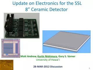
Update on Electronics for the SSL8” Ceramic Detector Matt Andrew, Kurtis Nishimura, Gary S. Varner University of Hawai’i 28-MAR-2012 Discussion
These items mainly impact the firmware/software, but having answers would expedite getting 8” ceramic PMT-specific development started Discussion Items Self-trigger operation required? Confirm PMT gain (1pC 6x10⁶) Maximum sustained rate (triggers, occupancy) Multi-hit buffering? How data to be rendered? (online) Yes. 0.5 – few pC (3x10⁶ – few x107) 200-300kHz (single hits?) Yes, if possible. Topic for discussion Wednesday (SSL/Berkeley guys to join)
On schedule for June integration with 8” ceramic MCP-PMT • Use existing ASICs, boards where possible • Leverage few man-years of development for Belle II • Board status • Pre-amps in hand, need test (enough boards if design) • ASIC daughtercard (will choose IRS2/IRS3 depending on performance [IRS3 in test]) • Interface board in layout (to be submitted in a week or two) • SCROD Rev. A in hand; firmware/software exists for readout • Integration plan • As components available, send to Berkeley for check • Integration “pow-wow” ~ RT2012 Conference Schedule/Plans
Ceramic design 8” Ceramic PMT @ SSL Conductive epoxy row of GND pins Discrete pig-tail for HV pins
From presentation/discussion in December:4x boards: (1) amp, (2) DC, (3) Interface, (4) SCROD (1) 4-channel “pre-amps” 18 needed (4) SCROD (Control, Readout) 1 needed (2) 8-channel “daughtercards” 9 needed Power Interface board (wiring, power) 1 needed monitoring
Short ribbon-cable jumpers to reduce strain on pin array Top view: Sample sent to Jason for mechanical check (1) Pre-amp cards: isolation, not just gain Bottom-less socketed pins (slide over signal/ground pins) Bottom view:
2x options (plug into same pair 80-pin SMT connector) (2) Daughtercards (8-ch ASICs underneath) IRS2 DC (better thermal management) IRS3 DC (better thermal management)
(3) Interface board (mostly “just” wiring) SCROD interface Schematics completed, routing started
(4) SCROD – small “pre-production run” For details: http://code.google.com/p/idlab-scrod/
Belle II iTOP Readout 8 COPPER BLAB waveform sampling ASIC 64 SRM 64 DAQ fiber transceivers 32 DSP FINESSE 32 FINESSE 8 COPPER 9 TRGmod 8k channels 1k 8-ch. ASICs 64 SRM “board stacks” Clock jitter cleaners 16 FTSW FTSW clock, trigger, programming 64 SRM
Readout “board stack” SL10 pulse with TOP electronics prototype (2.7 GSa/s) 12
Now a variety of WFS ASIC options… • Success of PSEC3: proof-of-concept of moving toward smaller feature sizes. • Next DRS plans to use 110nm; next SAM plans to use 180 nm.